-9-
STEP 6
6-2.
6-1.
Take the burner head with hose already attached and feed
the hose down into the
main pole
Attach the top section of the main pole with 4pcs 3/16” screws.
.
6-3. Fix the completed burner unit to the
main pole by 4pcs M6x10mm
bolts; ensure "Heater Operation Label" faces the same way
as the gas controls.
6-4.
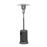
STEP 4
4-1. Assemble the bottom section of the main pole on top of 3pcs support legs.
4-2. Use 6 pcs M6 x 30 mm bolts and nuts to connect the main pole to the
3 pcs support legs .Tighten the bolts and nuts.
Main pole
Nut
STEP 4
Bolt
Bolt
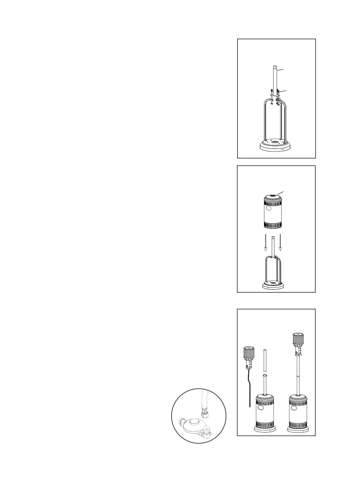
STEP 5
STEP 6
Tank housing
STEP5
Place the tankhousingon thestand. If your tank housing has a protective
plastic coating, please remove before operating the heater.
Attach the supplied regulator to the hose end and
tighten the connection with 2 spanners.