Do you have a question about the JUMO ATHs-SE-20 and is the answer not in the manual?
Explains symbols for danger, caution, notes, references, footnotes, and actions.
Details approved applications on ships and compliance with DIN EN 14597 and classification societies.
Specifies that thermostats are approved per DIN EN 60730-2-9.
Addresses risks from filling liquid leakage and provides toxicological data for potential exposure.
Illustrates a typical nameplate, detailing model, range, and certifications.
Breaks down the product's type code structure for basic type, extension, and design.
Provides detailed dimensional drawings and specifications for various models.
Step-by-step guide for safely opening and closing the thermostat housing.
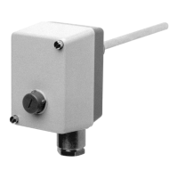
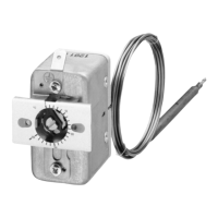
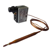
Explains how to fix the thermostat based on operating position and model type (stem or capillary).
Details on capillary bending, probe submersion, and sheath compatibility for optimal accuracy.
Specifies compatible connection types for temperature probes and sheaths.
Presents maximum permissible pressure ratings for stainless steel and brass sheaths at various temperatures.
Guidance on ensuring full submersion of the probe and sheath for accurate readings.
Details on qualified personnel, cable selection, and VDE regulations for electrical connections.
Instructions for connecting cables, terminals, and protective conductor, with diagrams and torque specs.
Guide to correctly seating the gasket, aligning components, and securing the case.
Details on sealing the cable inlet and providing strain relief for vibration protection.
Guide on how to open the case and use the set point setter to adjust the limit value.
Procedure for resetting the STB after it has tripped.
Details on system breakage behavior, low temperature response, and automatic unlocking.
Information on restart lock compliance with DIN EN 14597 and VDE 0116.
Comprehensive data on ambient temperature, overtemperature safety, contact ratings, protection, and time constants.
Information on available documentation, including conformity declarations and certificates.
This document describes the JUMO Series ATH.-SE-.. surface-mounting thermostats, which are designed for monitoring installations, particularly on steel-hulled ocean-going ships, including steam and boiler plants and indirect heating systems. These thermostats are approved for use as temperature monitors (TW), safety temperature monitors (STW/STB), and safety temperature limiters (STB). They comply with DIN EN 14597 and are approved by classification societies such as DNV GL and Bureau Veritas, as well as the Pressure Equipment Directive 2014/68/EU for specific models.
The JUMO ATH.-SE-.. thermostats operate as automatic modes (Type 2BL for TW, Type 2BK for STB/STW) with microswitch disconnection during operation, requiring no auxiliary energy source. The STB and STW (STB) versions also feature a fail-safe facility. In the event of a measuring system breakage (leakage), the circuit for both STB and STW (STB) remains permanently open. For the STB, the microswitch is additionally locked, requiring manual unlocking if the minimum probe temperature is exceeded. The STW (STB), however, unlocks itself automatically under the same conditions. The electrical circuit opens when the probe is cooled down to the negative temperature range, but it closes again if the temperature rises.
The device's core function involves setting a limit value for temperature monitoring. Once the temperature falls below this set limit value (safe temperature limit) by approximately 10% of the scale range, the microswitch can be reset. For thermostats with code -70, an external reset button is provided, which must align precisely with the internal reset button of the microswitch for proper operation.
The thermostats are designed for surface mounting and can be installed in an unrestricted operating position, with open-air mounting available upon request. The temperature probe must be completely submerged in the medium for accurate response. It is crucial to use the temperature probe with JUMO-supplied sheaths, as using other sheaths will invalidate the approval. Only probes with a diameter of 8 mm may be fitted into sheaths with a diameter of 10 mm. For applications where air is the operating medium, connection type "10" (without sheath) should be selected.
The device features a set point setter for adjusting the limit value using a screwdriver. The set point indicator, scale division, top stop, and bottom stop are clearly marked on the device for ease of use.
Maintenance primarily involves ensuring correct assembly and electrical connections. When opening the case, it is essential to unscrew the two lead-sealable cheese-head screws and carefully remove the upper part. During reassembly, the gasket in the lower part of the case must be seated correctly to ensure proper sealing. The upper part of the case is then placed onto the lower part, and the lead-sealable cheese-head screws are tightened.
For electrical connection, the connection cable (with a diameter between 10 and 16.5 mm and a maximum conductor cross-section of 2.5 mm²) is passed through the screw connection. The connection to the terminals and the protective conductor (PE terminal) must be established according to the provided connection diagrams. The clamping screws and protective conductor terminal (PE) require a specific tightening torque of 0.45 to 0.68 Nm. The screw connection for the cable inlet must be turned clockwise until the cable is sealed and secured against pulling out. Sufficient extra cable length should be left to protect against vibration overload.
A critical note for maintenance and usage is to avoid cutting through or kinking the capillary, as this will lead to permanent failure of the instrument. The minimum permissible bending radius for the capillary is 5 mm.
The device is protected to IP54 as per EN 60 529, ensuring operation under normal conditions. The case is made of aluminum die casting with screws for lead sealing for the cover and die-cast aluminum, painted, for the base.
The operating manual emphasizes that all necessary settings and alterations inside the instrument are described within the instructions. Users are advised against unauthorized manipulations to avoid endangering their rights under the instrument warranty. In case of difficulties during commissioning, users should contact the nearest subsidiary or the main factory. The electrical connection must only be made by qualified personnel, adhering to VDE 0100 regulations and local requirements. The instrument must be completely disconnected from the supply if contact with live parts is possible during work. Earthing the instrument at the PE terminal to the protective conductor is mandatory, with the earth cable having a cross-section at least as large as the supply cables and run in a star configuration to a common earth point. Incorrect settings can affect process functioning or lead to damage, thus setting up must be restricted to qualified personnel.
| Power supply | 24 V AC/DC |
|---|---|
| Protection type | IP65 |
| Temperature range | -30 to +70 °C |
| Electrical connection | Screw terminals |
| Housing material | Plastic |
| Measuring range humidity | 0 to 100 %RH |
| Accuracy | ±0.5 °C, ±3 % RH |
| Probe type | Integrated sensor |
| Measuring range temperature | -30 to +70 °C |