Inhalt
1 Introduction .................................................................................. 5
1.1 Typographical conventions ......................................................................... 5
1.1.1 Warning signs ................................................................................................. 5
1.1.2 Indicative signs ............................................................................................... 5
1.2 Application .................................................................................................... 6
1.3 Identification ................................................................................................. 6
1.4 Safety information ........................................................................................ 7
2 Identifying the device .................................................................. 8
2.1 Type plate (example) .................................................................................... 8
2.2 Type designation .......................................................................................... 8
3 Installation .................................................................................... 9
3.1 Dimensions ................................................................................................... 9
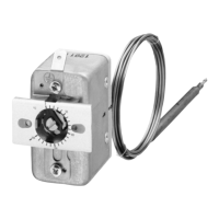
3.2 Fastening the panel-mounting thermostat .............................................. 10
3.2.1 Fasting the switching head .......................................................................... 10
3.3 Capillary / temperature probe / sheath .................................................... 11
3.3.1 General information ...................................................................................... 11
3.3.2 Approved process connections ................................................................... 12
3.3.3 Sheath made of steel 22, 23, 32, 41, 42 and 45 .......................................... 12
3.3.4 Sheath made of stainless steel 20, 22, 40 and 41 ....................................... 14
3.3.5 Sheath made of brass 20 and 40 ................................................................. 14
3.3.6 Probe connections 50, 52 and 54 ................................................................ 14
4 Installation .................................................................................. 16
4.1 Standards and information ........................................................................ 16
4.2 Electrical connection ................................................................................. 16
4.3 Wiring diagrams ......................................................................................... 17
5 Settings ....................................................................................... 18
5.1 Unlocking the safety temperature limiter (STB) ...................................... 18
5.2 Limit value setting ...................................................................................... 19
5.3 Self-monitoring of the STB and STW (STB) ............................................. 19
5.4 Use of the STW (STB) as STB .................................................................... 19
6 Device Description .................................................................... 20
6.1 Technical data ............................................................................................. 20