65
8 Device Manager
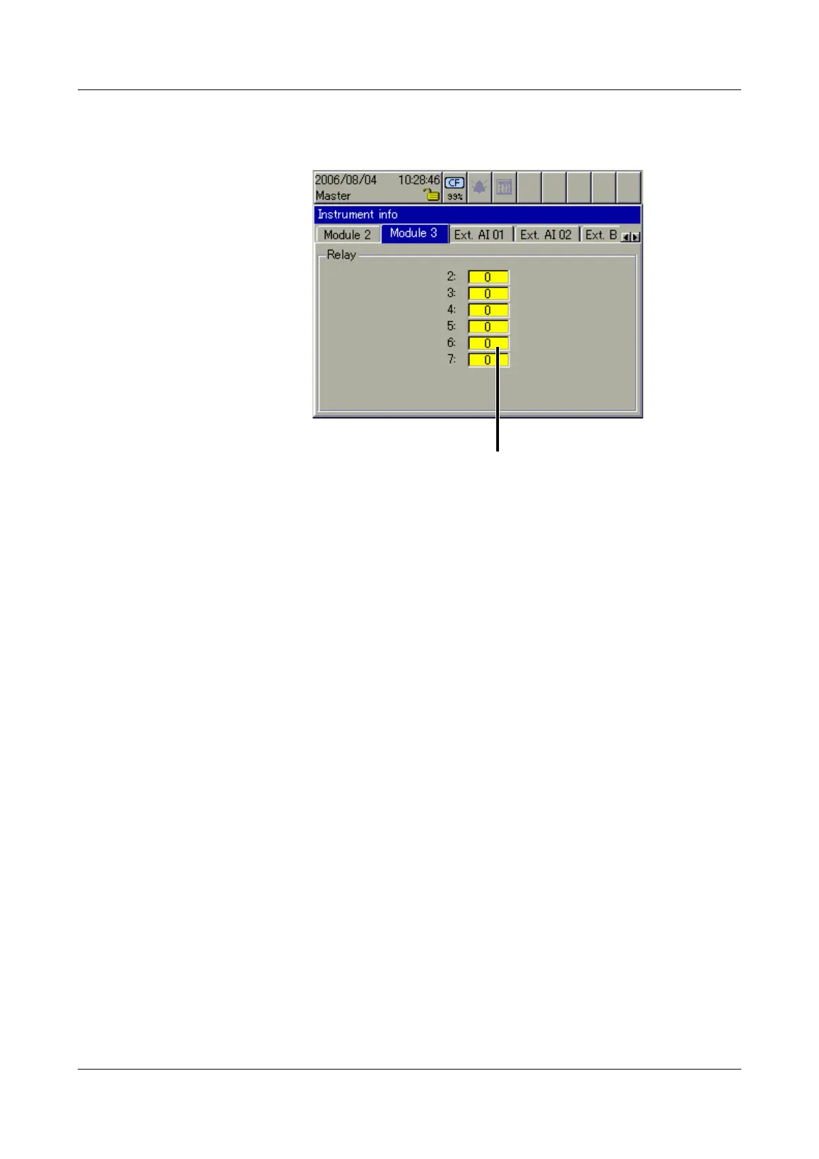
Module 3 The picture below shows a module that has been fitted with a relay card
(6 relays). Depending on the hardware level, the picture may look different.
Module 3 is in the top slot.
Ext. analog
input (AE) 1 — 2
The two windows show the current external analog inputs. External analog
inputs are read into the recorder via one of the interfaces (e.g. through the
Modbus Master function).
Ext. binary input
(BE)
The window shows the current external binary inputs. External binary inputs
are read into the recorder via one of the interfaces (e.g. through the Modbus
Master function). Unlike the internal binary inputs/outputs, external binary
outputs are not available.
Ext. texts The three windows show the current external texts, which can be integrated
into the batch reports as label or information text. External texts are read into
the recorder via one of the interfaces (e.g. through the Modbus Master
function).
Switching state of relays
(0 = not switched).