23
4 Electrical connection
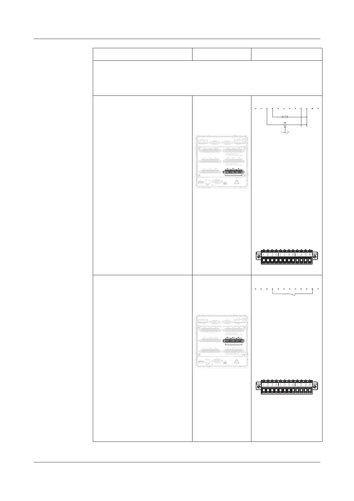
Binary inputs/
outputs
H The configuration in the instrument or in the setup program
defines whether it is a binary input or binary output.
B1 … B8
voltage-controlled
LOW = -3 to +5V DC
HIGH = 12 to 30V DC
B1 Binary input/output 1
B2 Binary input/output 2
B3 Binary input/output 3
B4 Binary input/output 4
B5 Binary input/output 5
B6 Binary input/output 6
B7 Binary input/output 7
B8 Binary input/output 8
U
in
+external supply
voltage
U
in
- ground
U
out
++24V (60mA) internal
supply voltage
U
out
- ground
Connector 9
only for modules
with 3 analog
inputs
Example:
Connecting a load to
binary output 4 (B4)
and a solid-state
relay to binary
output 3 (B3) requires
an external supply
voltage.
Diagram of the
connector:
B9 … B16
voltage-controlled
LOW = -3 to +5V DC
HIGH = 12 to 30V DC
B9 Binary input/output 9
B10 Binary input/output 10
B11 Binary input/output 11
B12 Binary input/output 12
B13 Binary input/output 13
B14 Binary input/output 14
B15 Binary input/output 15
B16 Binary input/output 16
U
in
+external supply
voltage
U
in
- ground
U
out
++24V (60mA) internal
supply voltage
U
out
- ground
Connector 11
only for modules
with 3 analog
inputs
Example:
Binary input 12 (B12)
is operated from the
internal supply
voltage.
Diagram of the
connector:
Terminal assignment Connector Diagram
13
14
15
16
17
18
4
3
2
1
B20
B17
B18
B19
B21
B22
B23
B24
B12
B 9
B10
B11
B13
B14
B15
B16
B4
B1
B2
B3
B5
B6
B7
B8
+
+
U
U
U
+
+
U
U
+
+
U
-
-
-
-
-
-
in
out
in
out
in
out
1
2
3
4
1
2
3
4
1
2
3
4
9
8
7
1
2
3
4
10 11
1
2
3
4
1
2
3
4
12
1
2
3
4
1
2
3
4
1
2
1
2
3
4
3
1
2
3
4
1
2
3
4
1
5
4
2
3
4
6
11
22
33
44
1
2
3
4
11
22
33
44
12.
13.
11.
9.
8.
10.
3.
2.
1.
12
13
11
5.
6.
7.
PE
N
L1
(L+)
(L-)
4.
15.
B4
B1
B2
B3
B5
B6
B7
B8
+
+
U
U
-
-
in
out
1
2
3
4
1
2
3
4
1
5
4
2
3
4
6
9.
B2
B3
B4
B5
B6
B7
B8
+
-+
B1
-
U
in
U
out
+-
24V external
supply voltage
Load
B1
B2
B3
B4
B5
B6
B7
B8
Uin+
Uin-
Uout+
Uout-
13
14
15
16
17
18
4
3
2
1
B20
B17
B18
B19
B21
B22
B23
B24
B12
B 9
B10
B11
B13
B14
B15
B16
B4
B1
B2
B3
B5
B6
B7
B8
+
+
U
U
U
+
+
U
U
+
+
U
-
-
-
-
-
-
in
out
in
out
in
out
1
2
3
4
1
2
3
4
1
2
3
4
9
8
7
1
2
3
4
10 11
1
2
3
4
1
2
3
4
12
1
2
3
4
1
2
3
4
1
2
1
2
3
4
3
1
2
3
4
1
2
3
4
1
5
4
2
3
4
6
11
22
33
44
1
2
3
4
11
22
33
44
12.
13.
11.
9.
8.
10.
3.
2.
1.
12
13
11
5.
6.
7.
PE
N
L1
(L+)
(L-)
4.
15.
B12
B 9
B10
B11
B13
B14
B15
B16
U
+
+
U
-
-
in
out
1
2
3
4
10 11
1
2
3
4
1
2
3
4
12
11.
B10
B11
B12
B13
B14
B15
B16
+
-+
B9
-
U
in
U
out
B9
B10
B11
B12
B13
B14
B15
B16
Uin+
Uin-
Uout+
Uout-

 Loading...