4 Electrical connection
24
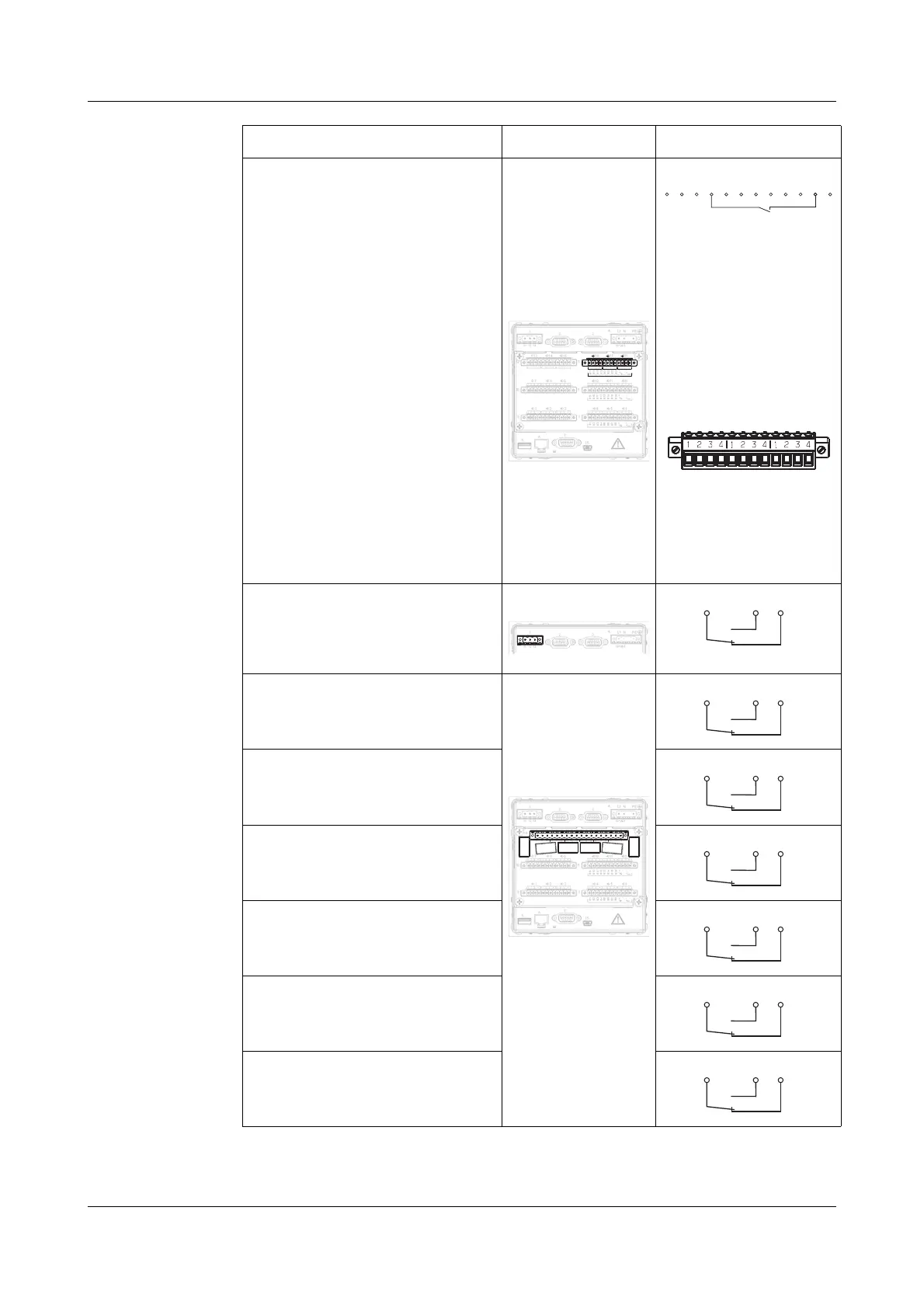
Binärein-/
-ausgänge
B17 … B24
voltage-controlled
LOW = -3 to +5V DC
HIGH = 12 to 30V DC
B17 Binary input/output 17
B18 Binary input/output 18
B19 Binary input/output 19
B20 Binary input/output 20
B21 Binary input/output 21
B22 Binary input/output 22
B23 Binary input/output 23
B24 Binary input/output 24
U
in
+external supply
voltage
U
in
- ground
U
out
++24V (60mA) internal
supply voltage
U
out
- ground
Connector 13
only for
instrument
variant 2
and on modules
with 3 analog
inputs
Example:
Binary input 20 (B20)
is operated from the
internal supply
voltage.
Diagram of the
connector:
Relay outputs Relay 1 - alarm
changeover (SPDT)
Connector 1
Relay 2
changeover (SPDT)
Connector 14
only for
instrument
variant 1
Relay 3
changeover (SPDT)
Relay 4
changeover (SPDT)
Relay 5
changeover (SPDT)
Relay 6
changeover (SPDT)
Relay 7
changeover (SPDT)
Terminal assignment Connector Diagram
13
14
15
16
17
18
4
3
2
1
B20
B17
B18
B19
B21
B22
B23
B24
B12
B 9
B10
B11
B13
B14
B15
B16
B4
B1
B2
B3
B5
B6
B7
B8
+
+
U
U
U
+
+
U
U
+
+
U
-
-
-
-
-
-
in
out
in
out
in
out
1
2
3
4
1
2
3
4
1
2
3
4
9
8
7
1
2
3
4
10 11
1
2
3
4
1
2
3
4
12
1
2
3
4
1
2
3
4
1
2
1
2
3
4
3
1
2
3
4
1
2
3
4
1
5
4
2
3
4
6
11
22
33
44
1
2
3
4
11
22
33
44
12.
13.
11.
9.
8.
10.
3.
2.
1.
12
13
11
5.
6.
7.
PE
N
L1
(L+)
(L-)
4.
15.
16
17
18
B20
B17
B18
B19
B21
B22
B23
B24
U
+
+
U
-
-
in
out
1
2
3
4
11
22
33
44
13.
B18
B19
B20
B21
B22
B23
B24
+
-+
B17
-
U
in
U
out
B17
B18
B19
B20
B21
B22
B23
B24
Uin+
Uin-
Uout+
Uout-
3.
2.
1.
12
13
11
PE
N
L1
(L+)
(L-)
4.
1.
12
13
11
21
22
23
31
32
33
41
42
43
51
52
53
61
62
63
71
72
73
1
2
3
4
10 11
12
1
2
3
4
5
6
9
8
7
B12
B 9
B10
B11
B13
B14
B15
B16
B4
B1
B2
B3
B5
B6
B7
B8
+
+
+
U
U
+
-
-
--
in
out
U
U
out
U
U
in
33
44
11
22
1
2
3
4
1
2
3
4
1
2
3
4
1
2
3
4
1
2
3
4
1
2
3
4
1
2
3
4
1
2
3
4
1
2
3
4
8.
9.
11.
10.
14.
3.
2.
1.
12
13
11
5.
6.
7.
PE
N
L1
(L+)
(L-)
4.
15.
21
22
23
31
32
33
41
42
43
51
52
53
61
62
63
71
72
73
14.

 Loading...