Do you have a question about the Jung KNX and is the answer not in the manual?
Device is a KNX system product. Detailed technical knowledge of KNX is a prerequisite.
Specifies the intended applications for switching consumers, blinds, shutters, and heating outputs.
Lists features like manual output control, scene function, and disabling outputs.
Details logic operations, forcing functions, and time functions for switching.
Covers direct control of position, slat adjustment, and safety functions for blinds/shutters.
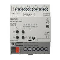
Explains switching or PWM operation, overload protection, and emergency operation for valve drives.
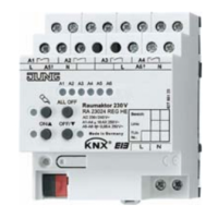
Describes the function of manual control keys and status LEDs on the device.
Explains how output status LEDs indicate device states like on, off, or manual control mode.
Details bus operation, temporary manual control, and permanent manual control modes.
Outlines the priority order for manual control, forced-control, safety, and bus operations.
Steps to activate temporary manual control using the keypad and its automatic return to bus mode.
Methods to deactivate temporary manual control by key-press or timeout.
Procedure to activate permanent manual control mode using a long key-press.
Procedure to deactivate permanent manual control mode by a long key-press.
Instructions on how to operate outputs in manual control modes using keys and LEDs.
Procedure to switch off all outputs simultaneously using the ALL OFF key.
Steps to disable specific outputs using key combinations in permanent manual control mode.
Instructions on how to mount the device onto a DIN rail and considerations for heat dissipation.
Diagram and steps for connecting the bus line and mains voltage supply to the device.
Details on connecting switched loads, emphasizing parameterization as a switching output.
Explains using adjacent relay outputs for blind/shutter drives, specifying directions.
Guidance on connecting electro-thermal valve drives, including maximum per output and characteristics.
Instructions for fitting the protective cap onto the bus terminal.
Explains the importance of measuring blind/shutter and slat adjusting times for positioning.
Steps to assign a physical address and download application software after switching on bus voltage.
Provides specifications for KNX medium, supply, voltage, frequency, temperature, and weight.
Specifies wire cross-section requirements for connecting terminals and outputs.
Details technical specifications for heating output connections and types.
Provides technical specifications for relay output contact types and switching parameters.
Details the load ratings for various types of loads connected to the relay outputs.
Troubleshooting steps for when manual control via keypad is not functioning.
Troubleshooting steps for when device outputs are not responding.
Troubleshooting for situations where all outputs are disabled or the device is unresponsive.
Troubleshooting steps for when communication or operation via the bus is not possible.
| Protection Class | IP20 |
|---|---|
| Product Type | Controller |
| Mounting | DIN Rail Mounting |
| KNX Medium | TP |
| Current Consumption | 10 mA |
| Operating Temperature | -5°C to +45°C |
| Weight | 100 g |
| Bus Voltage | 21-30V DC |