KNX Room actuator 230 V
Ref.-no.: RA 23024 REGHE
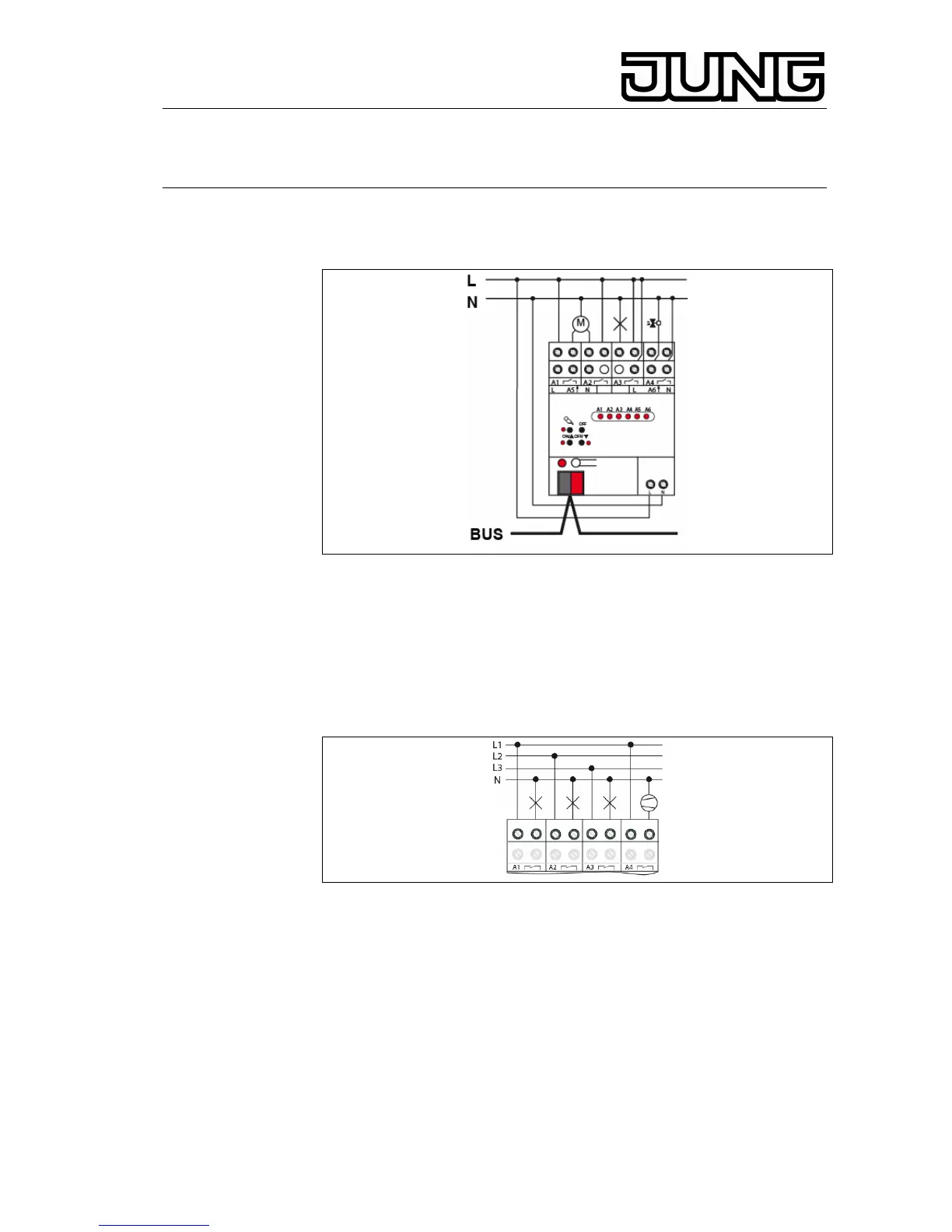
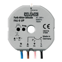
5.2 Connecting the device
Fig.3: Connection
• Connect the bus line to the bus terminal.
• Connect the mains voltage supply.
• Connect the loads as described in the following chapters.
L Delivery state: provisional operation possible, output control via keypad
enabled, All outputs are configured as shutter outputs.
5.3 Connecting switched loads
Fig. 4: Connection of switched loads
The output must be parameterized as switching output.
• Connect the switched loads (Fig. 4). Do not exceed the permissible load
ratings (Technical data).
5.4 Connecting blind/shutter drives
For blind/shutter operation, two adjacent relay outputs are used as a
blind/shutter output. The left relay output A1, A3 is intended for the upward
direction and the right relay output A2, A4 for the downward direction.
8