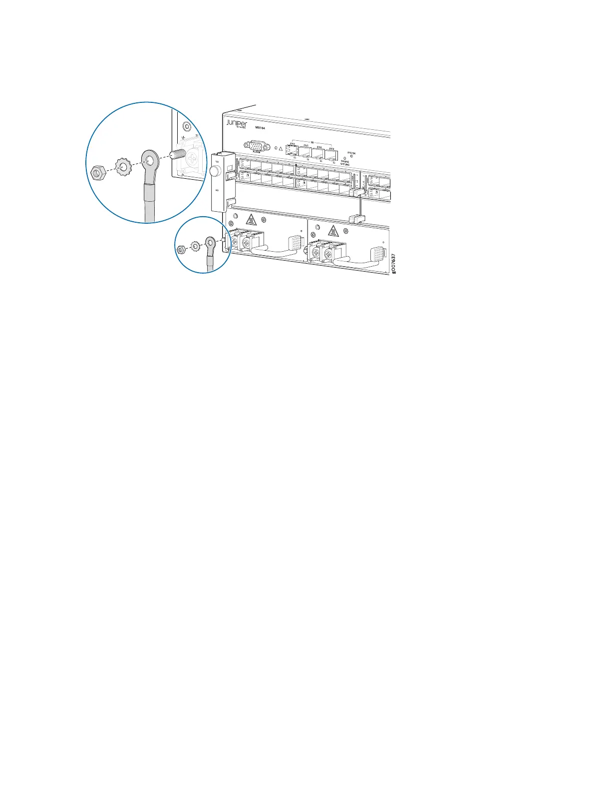
Figure 10: Connecting the Ground Cable to the MX104 DC Power Supply
3. Remove the plastic cover protecting the terminal on the faceplate.
4. Verify that the DC power cables are correctly labeled before making connections to the power supply.
In a typical power distribution scheme where the return is connected to chassis ground at the battery
plant, you can use a multimeter to verify the resistance of the –48V and return DC cables to chassis
ground:
For –48V and –60V:
a. The cable with very high resistance (indicating an open circuit) to chassis ground is the DC input
cable (-).
b. The cable with very low resistance (indicating a closed circuit) to chassis ground is the return cable
(+).
For +24V:
a. The cable with very low resistance (indicating a closed circuit) to chassis ground is the DC input
cable (-).
b. The cable with very high resistance (indicating an open circuit) to chassis ground is the return cable
(+).
5. Remove the screws and washers from the DC terminals.
6. Secure each power cable lug to the terminal with the washers and screw (see Figure 11 on page 20).
Apply 27.4 lb-in. (3.1 Nm) of torque to each screw. Do not overtighten the screw. (Use a number 2
Phillips screwdriver.)
a. Secure the positive DC source power cable lug to the return (+) terminal.
b. Secure the negative DC source power cable lug to the input (–) terminal.
18