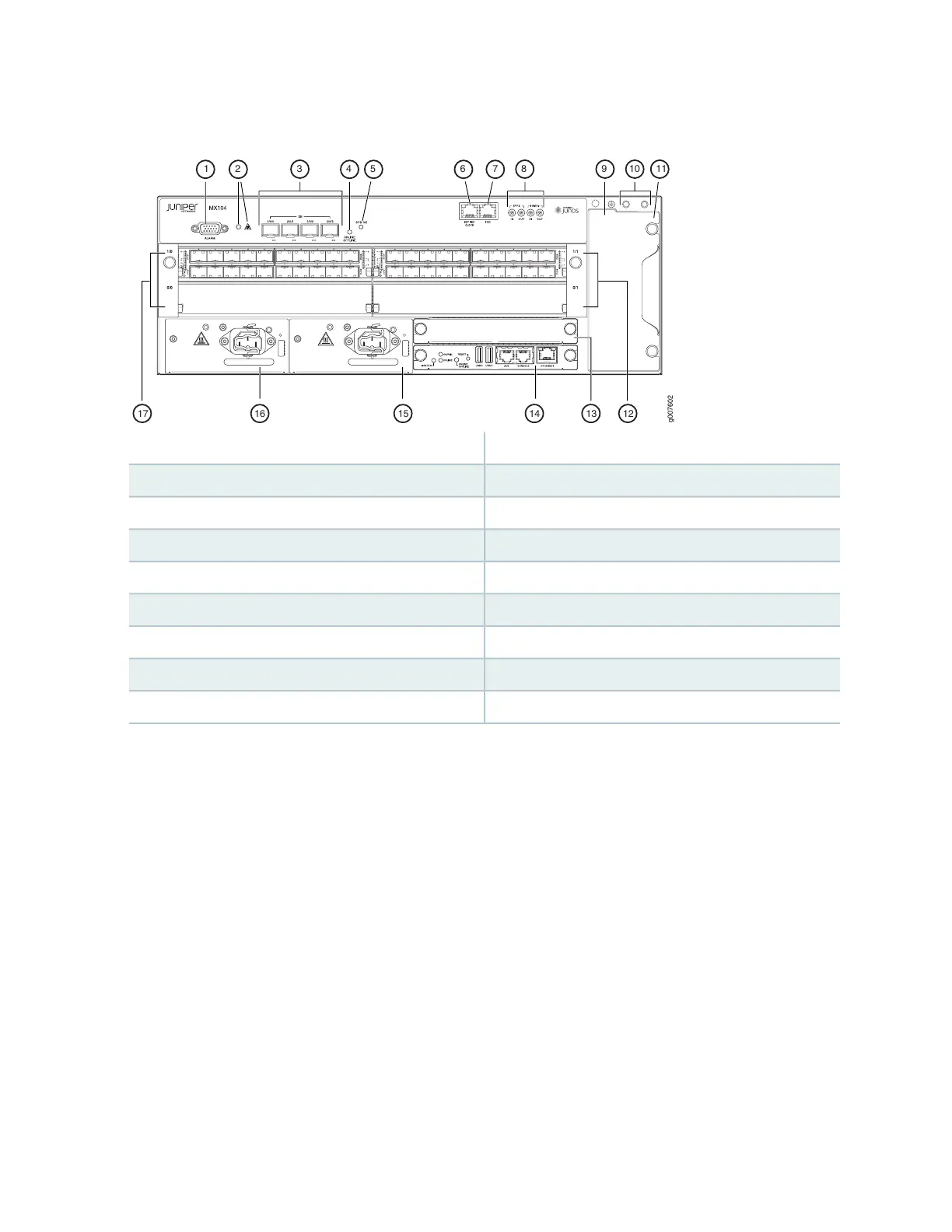
Figure 1: Front View of the MX104 Router
g007602
17 16 15 1314 12
31 54 10 1198762
10—1— Grounding terminalsAlarm input and output contacts
11—2— Fan trayAlarm LEDs
12—3— MIC slots 0/1 and 1/110-Gigabit Ethernet SFP+ ports
13—4— Routing EngineONLINE/OFFLINE button
14—5— Routing EngineSystem status LED
15—6— Power supplies (AC or DC)External reference clocking port
16—7— Power supplies (AC or DC)Time-of-day (TOD) port
17—8— MIC slots 0/0 and 1/01-PPS and 10-MHz GPS input and output ports
9—ESD point
4