Step 5: Connect External Devices and DPC or PIC Cables
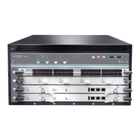
Figure 8: Routing Engine Management Ports
•
Connect to a Network for Out-of-Band Management on page 15
•
Connect a Management Console on page 15
•
Connect the Line Card Cables on page 15
Connect to a Network for Out-of-Band Management
1. Turn off the power to the management device.
2. Plug one end of the RJ-45 Ethernet cable into the appropriate ETHERNET port on the
Routing Engine.
3. Plug the other end of the cable into the network device.
Connect a Management Console
1. Turn off the power to the management device.
2. Plug the RJ-45 end of the serial cable into the appropriate CONSOLE or AUX port on
the Routing Engine.
3. Plug the female DB-9 end of the serial cable into the device's serial port.
Connect the Line Card Cables
1. Have ready a length of the type of cable used by the line card. For cable specifications,
see the MX Series Interface Module Reference.
2. If the cable connector port is covered by a rubber safety plug, remove the plug.
WARNING: Do not look directly into a fiber-optic transceiver or into the
ends of fiber-optic cables. Fiber-optic transceivers and fiber-optic cable
connected to a transceiver emit laser light that can damage your eyes.
CAUTION: Do not leave a fiber-optic transceiver uncovered except when
inserting or removing cable. The safety cap keeps the port clean and
prevents accidental exposure to laser light.
15Copyright © 2015, Juniper Networks, Inc.
Step 5: Connect External Devices and DPC or PIC Cables

 Loading...