7. Rotate the captive screw away from the faceplate of the power supply to release the latch.
NOTE: You can install the power supplies in any slot labeled PSU 0 through PSU 5 (top to bottom) on a
PTX10008.
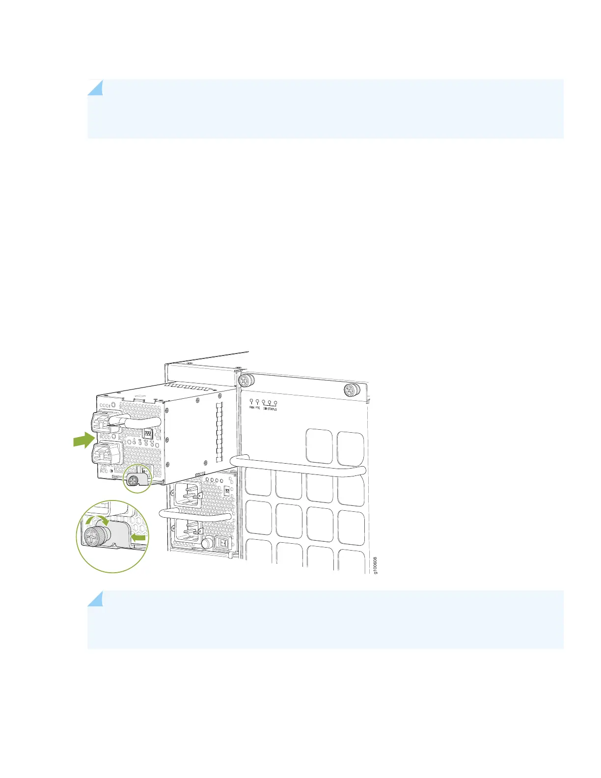
8. Using both hands, place the power supply in the power supply slot on the rear of the system. Slide the power supply
straight into the chassis until the power supply is fully seated in the slot. Ensure the power supply faceplate is flush
with any adjacent power supply faceplates or power supply covers (see Figure 26).
9. Push the captive screw into the power supply faceplate. Ensure that the screw is seated inside the corresponding hole
on the faceplate.
10. Tighten the captive screw by turning it clockwise by using the Phillips (+) screwdriver, number 1. When the screw is
completely tight, the latch locks into the router chassis.
Figure 26: Installing a JNP10K-PWR-AC2 in a PTX10008
NOTE: The power supply fans will start immediately when inserted into the chassis, even though a feed
is not yet connected.
11. Attach each power cable to a dedicated power (A and B). The JNP10K-PWR-AC2 only requires that each power supply
be connected to a separate source. See Figure 27 for some possible cabling combinations for PTX10008.
27