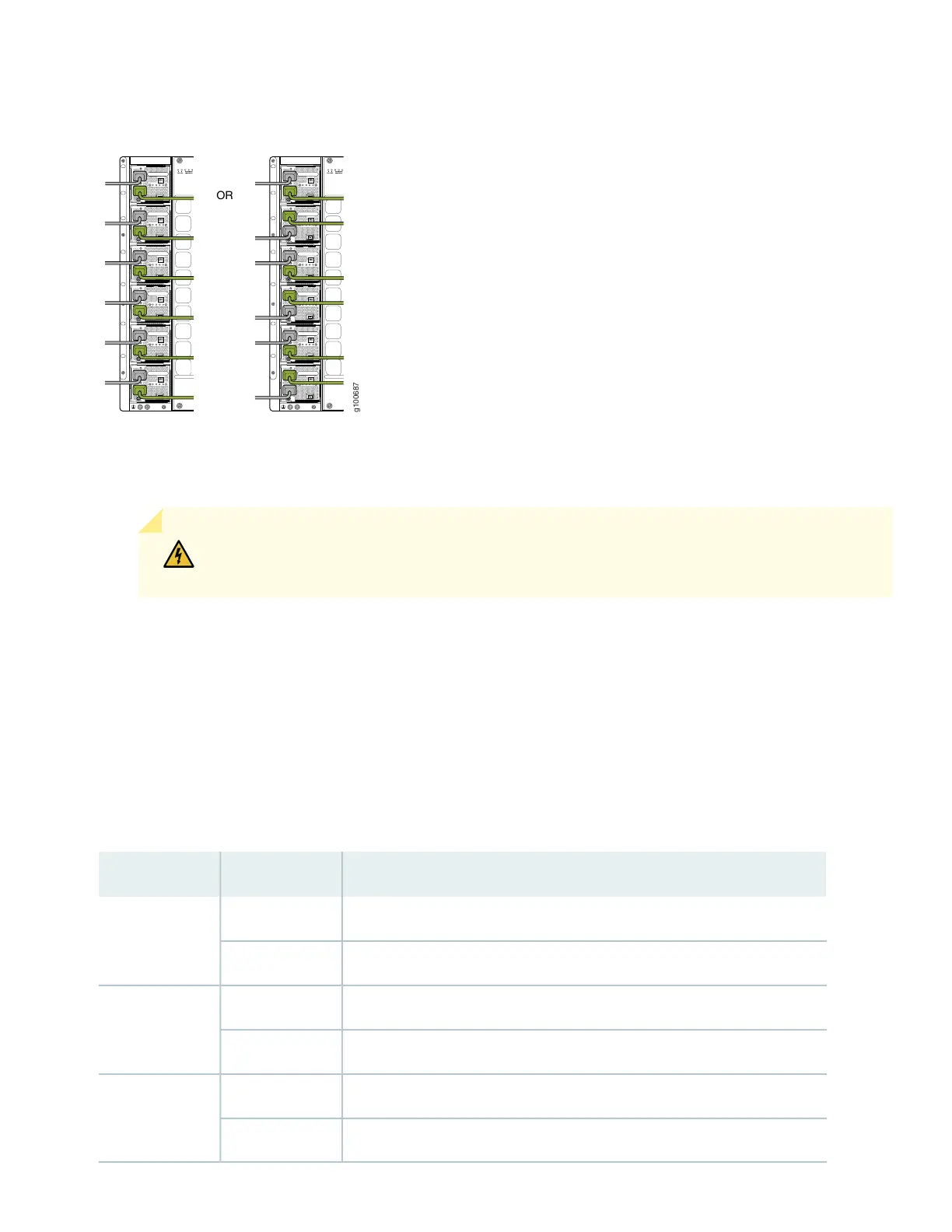
Figure 27: Proper Load Balancing for JNP10K-PWR-AC2 Power Cables on PTX10008
12. For each power cable, insert the end of the cable with the Anderson connector into the JNP10K-PWR-AC2 power
supply module. The connector snaps and locks the cable into position.
WARNING: Ensure that the power cords do not block access to router components or drape
where people can trip on them.
13. If the AC or DC power source outlets have a power switch, set them to the on (|) position.
14. Set the three dip switches to set the inputs and whether the power supply is running at 3000 W, 5000 W, or 5500 W.
See Table 2.
Set both enable switches to the on position when using both source inputs. When not using source redundancy, set
the unused source to the O (off) position. The LED turns red and indicates an error if a source input is not in use and
the enable switch is | (on).
Table 2: Setting the JNP10K-PWR-AC2 Dip Switches
FieldStateSwitch
IP0 is presentOn1
IP0 is not presentOff
IP1 is presentOn2
IP1 is not presentOff
Enabled for 30 A feed; 5000-W for a single feed, 5500-W for dual feedsOn3
Enabled for 20 A feed; power supply capacity is 3000-WOff
28