How to Set Up Your SRX300 Services Gateway
4
LED State
ALARM • Solid amber (noncritical alarm).
• Solid red (critical alarm).
• O (no alarms).
STAT • Solid green (operating normally).
• Solid red (error detected).
PWR • Solid green (receiving power).
• Solid red (power failure).
• O (no power).
HA • Solid green (all HA links are available).
• Solid amber (some HA links are unavailable).
• Solid red (HA links are not functional).
• O (HA is disabled).
Connect the Management Device
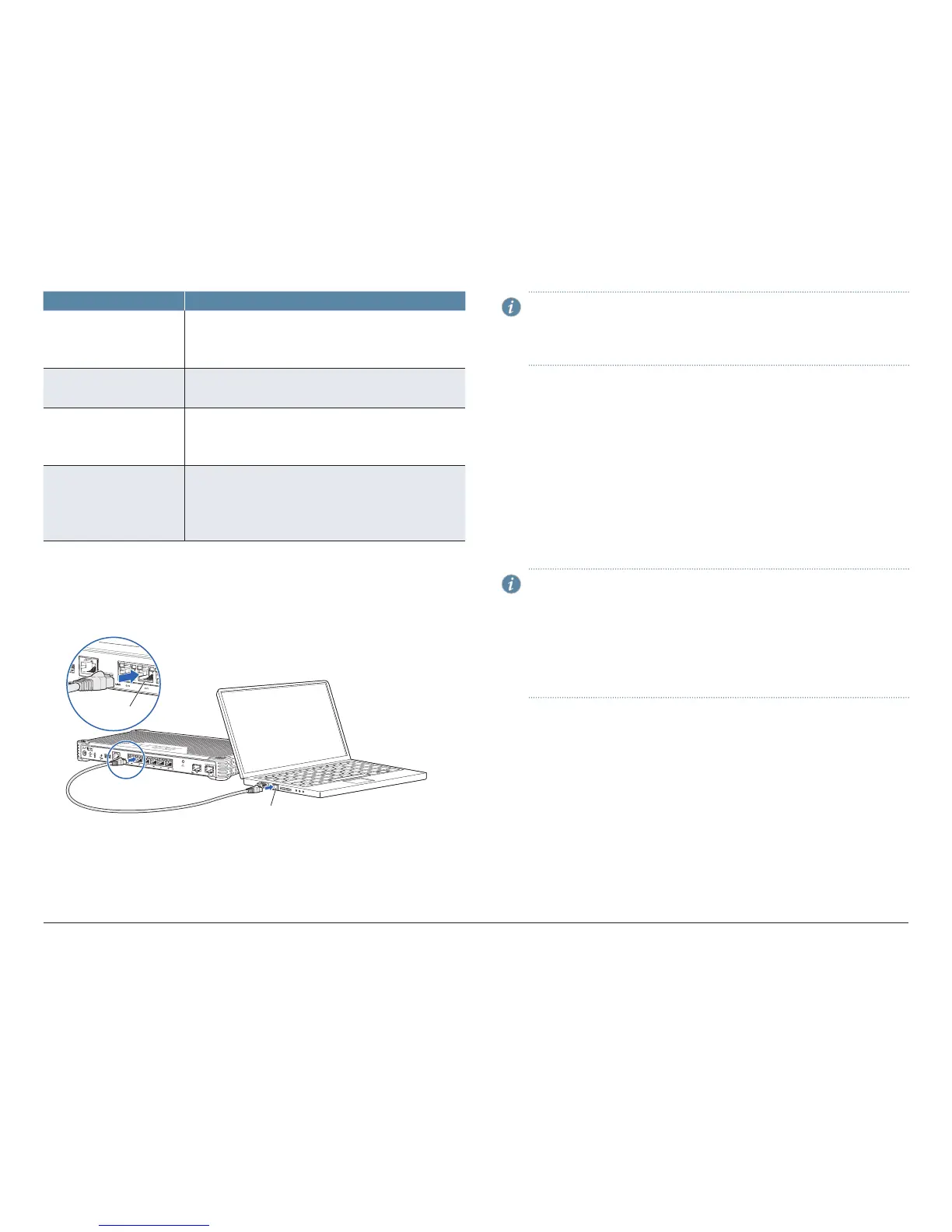
1. To configure the device using J-Web (recommended), connect any of the
network ports numbered 0/1 through 0/5 to the Ethernet port on the
management device, using an RJ-45 cable.
g000737
SRX300
RJ-45 cable
Ethernet port
Ethernet port
NOTE: The ge-0/0/0 interface (port 0/0) is a WAN interface. Do not
use this port for the initial configuration procedure.
If you will be using the Default setup mode to configure the device, use
only port 0/1. For information on the setup modes, see page 5.
2. Ensure that the management device acquires an IP address. The IP address
should be on the corresponding IP subnet for the interface you connected to
in step 1. The device functions as a DHCP server and will assign an IP address
to the management device.
For example, if you are connected to port 0/1, then the IP address of the
management device should be from the 192.168.1.x network. If an IP address
is not assigned to the management device, manually configure an IP address.
Do not assign the 192.168.1.1 IP address to the management device, as this IP
address is assigned to the device. You can use the ipconfig (or ifconfig for
Macintosh or Linux users) command to verify the IP address.
Refer to the Interfaces table on page 2 for information on the subnet for each
interface.
NOTE: To configure the device using the CLI, connect the RJ-45 cable
from the CONSOLE port to the supplied DB-9 adapter, which then
connects to the serial port on the management device (serial port
settings: 9600-N-1).
Alternately, you can use the USB cable to connect to the mini-USB
console port on the services gateway. To use the USB console port,
you must download a USB driver to the management device from
http://www.juniper.net/support/downloads/group/?f=junos.
 Loading...