12. Tighten the screws on either side of the card.
13. Reconnect the cables, if any, that you disconnected from the SFB front panel
connectors in Step 4.
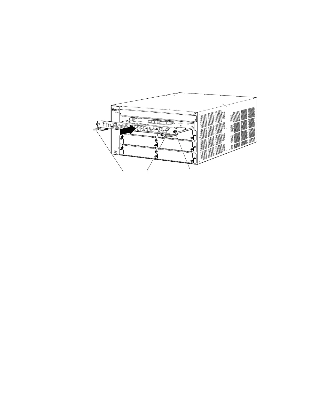
Figure 2: Inserting the SFB
g036060
Captive screwEjector levers
14. Power on the services gateway by pressing the Power button on the front panel
of the SFB for three to five seconds. Wait for the device to start.
15. Verify that the SFB is functioning normally by checking the LEDs on its faceplate.
The SFB STATUS LED should light steadily green a few minutes after the device
is powered on. If the SFB STATUS LED is red, remove and install the SFB again.
If the SFB STATUS LED still lights steadily red, the SFB is not functioning properly.
Contact your customer support representative.
To check the status of the SFB:
user@host> show chassis environment fpc 0
CB 0 status:
State Online Master
Temperature 30 degrees C / 86 degrees F
Power 1
1.2 V 1202 mV
1.5 V 1511 mV
1.8 V 1798 mV
2.5 V 2481 mV
3.3 V 3306 mV
5.0 V 4956 mV
12.0 V 12084 mV
1.25 V 1250 mV
3.3 V SM3 3287 mV
5.0 V RE 5046 mV
12.0 V RE 11910 mV
Power 2
11.3 V bias PEM 11292 mV
11.3 V bias FPD 11156 mV
11.3 V bias POE 0 11253 mV
11.3 V bias POE 1 11272 mV
Bus Revision 42
FPGA Revision 1
2 ■ Replacing the Switch Fabric Board on the SRX3600 Services Gateway