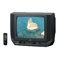
V-14FMG3/AV-14FMG3B
10
REPLACEMENT OF MEMORY ICs
1. MEMORY ICs
This mod el u ses memory I Cs. This me mo ry IC da ta are f or pro per opera tion of th e video a nd d eflect ion circuits.
When rep lacing me mory ICs, be su re to us e ICs writ ten with t he initial va lues of dat a.
2. PROCEDURE FOR REPLACING MEMORY ICs
(1) Power off
Switch the p ower of f and disco nn ect t he powe r plug f rom t he wall out let.
(2) Replace ICs
Be sure to use memory ICs written with the initial data values.
(3) Power on
Connect th e p ower plu g int o t he wall ou tlet and switch t he po we r on .
(4) Check and s et SY STEM CO NSTANT SET
・
・・
・ It must not adjust without adjustment signals.
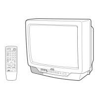
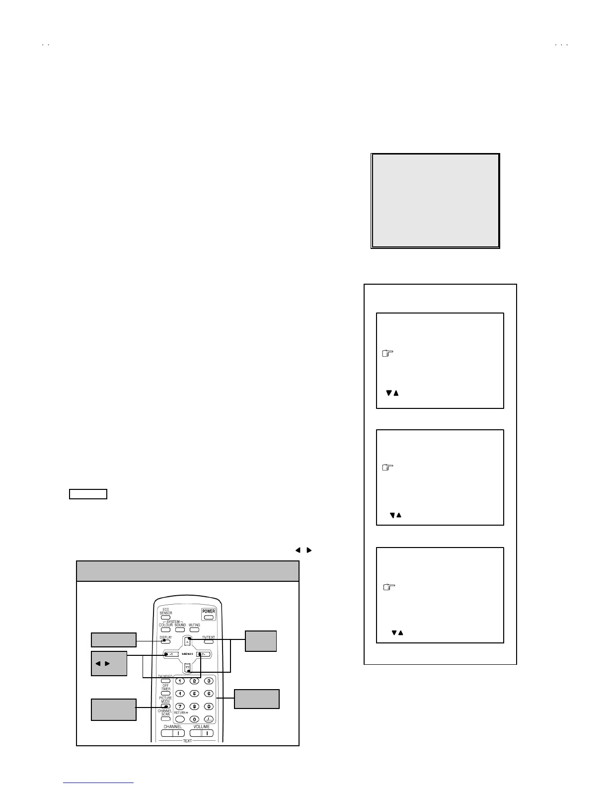
1) Pr ess th e DI SPLAY key and the PICTURE MODE key of the REMOTE
CONTROL UNIT simultaneously.
2) The SERVICE MENU screen of Fig. 1 will be displayed.
3) While th e SE RV ICE MENU is displayed , ag ain press the DI SPLAY key and
PICTURE MODE ke y simultaneo usly, an d t he S YSTEM CONSTA NT SE T
screen of Fig. 2 will b e displa ye d.
4) Check th e s ettin g value s of the S YSTE M CO NSTANT S ET o f T able 1 If th e
valu e is diffe re nt, select the sett ing it em with the MENU ▼/▲key, and set
th e co rrect valu e with t he MENU - / + k ey.
5) Pr ess the DISPLAY ke y twice, and retu rn t o th e n or m al scree n.
(5) Receive channel of setting
Refer to the OPERATI NG I NST RUCTIONS an d set th e r ece ive cha nn els
(chan ne ls pr eset) as descr ibe d
(6) User Setting
Check t he us er s ettin g valu e of Tab le 2, and if se tting value is dif feren t, set
th e co rrect valu e.
For se tting, ref er to the OPE RATI NG INSTRUCTIO NS .
(7) Setting of SERVICE MENU
Ve rif y the set ting it ems of th e SE RVICE MENU, and reset whe re n ecessa ry.
For se tting, ref er to the SERVICE ADJUSTMENTS.
NOTE
Althou gh th e k ey p osition of t he RM-C90 remote control u nit is diff erent from
th at of t he RM -C364GY & RM-C354 remot e control u nit, t he f unc tions of both
un its are th e same S o pleas e us e th e at tach ed d iagra m f or th e RM-C90
remote control unit for the RM-C364GY & RM-C364.
By t he way, MENU -/+ Key fu nctions in t he same mann er as for / key.
 Loading...