3
SAFETY PRECAUTIONS
1. The d esign of th is pr od uct con ta in s sp ecial hard wa re, many
circuits and components specially for saf ety purposes. For
con tinu ed prot ection , no chan g es sh ou ld b e ma de to the o rig inal
d esign un less a uth orized in writin g by th e manu fact urer.
Replacem en t p ar ts m ust be id ent ic al to thos e u sed in the origin al
circu it s. S ervice sho uld b e p erformed by qu alif ied p ers on nel
on ly.
2. Alte ration s of t he desig n or circuitr y of t he prod ucts sh ould not be
made. Any design alterations or additions will void the
manu fact urer 's warra nt y and will f ur th er relieve t he manu factu r er
of r esp onsib ility for per so na l injury or p r op er ty d am ag e r esult ing
th er efrom.
3. Man y e lectrical an d m ech anica l parts in th e prod ucts ha ve
special safety-relat ed characteristics. T hese characteristics are
oft en no t e viden t f rom visua l insp ection n or ca n t he pr o tect ion
aff orde d by th em nece ssarily b e ob tain ed b y u sing r ep lacemen t
compo ne nts ra ted f or hig he r vo ltag e, watt ag e, etc. Rep lacem en t
p arts whic h ha ve th ese sp ecial s afet y ch ar act er ist ics ar e
identified in the parts list of Servic e manual. El ec tric al
components having su ch features ar e identified by shading
on the sche matics and by (!
!!
! ) on the parts list in Service
manual. The us e of a sub stitute rep la cemen t which do es n ot
h ave th e same saf ety ch ar act er ist ics as t he r eco mmen de d
replac ement part shown in the p arts list of S er vice man ual m ay
cause shock, fire, or other hazards .
4. Do n't short between the LIVE side ground and ISOLATED
(NEUTRAL) side ground or EARTH side ground when
repairing.
Some model's power circuit is partly different in the GND. The
diff erenc e of the G ND is sho wn b y th e LIV E : (") side GND, the
ISO LATE D(NEUTRAL) : (#) side G ND and EARTH : ($) side
GND. Do n't shor t b et ween the LIV E sid e GND an d
ISO LATE D(NEUTRAL) side GND or EARTH sid e GND an d
n ever mea sure wit h a m ea sur ing a ppa ratus (oscillo scop e etc.)
th e LI VE sid e GND an d IS OLA TED(NE UTRAL) sid e G ND or
EARTH side GND at the s ame time.
If above note will not be kept, a fuse or any parts will be broken.
5. If any repair has been made to the chassis, it is recommended
th at t he B1 set ting shou ld b e ch ecke d or adju ste d (See
ADJUSTMENT OF B 1 POW E R SUPPL Y).
6. The high voltage app lie d t o th e pictu re tube must con for m wit h
th at sp ecified in S ervice man ual. E xcessive h igh vo lt ag e ca n
cau se an incre ase in X-Ray emission , arcing an d possib le
component damage, therefore operation under excessive high
voltage conditions should be kept to a minimum, or should be
preve nt ed. If s ever e arc ing occurs, remove t he AC power
immed iately an d de termine th e ca use b y visua l insp ect io n
(in corr ect installat ion, cracke d or melte d high vo lt age harn ess,
p oor so ld ering, et c.). To maint ain the p rope r min imu m le vel of
sof t X-Ray em ission, c ompon en ts in the high voltag e circuitry
includ ing t he pict ur e tu be must b e t he e xact rep laceme nts or
alte rnat ives ap pr oved b y th e ma nuf act urer of th e c omplet e
prod uct.
7. Do n ot c hec k high volt ag e b y dr awing an arc. Use a high volt ag e
meter or a hig h v oltage prob e wit h a V TVM . Discha rge th e
picture tube before attempting meter connection, by connecting
a clip lead to th e grou nd f rame a nd c onn ectin g the oth er end of
the lead through a 10kΩ 2W resistor to the an od e b utt on .
8. W hen se r vice is requ ire d, obser ve th e or igina l lea d dress. E xtr a
prec aut ion sh ou ld b e g ive n t o assure correct lea d dress in th e
high voltag e circuit a rea. W her e a s hort circuit h as occu rre d,
th ose comp on ent s that indica te evide nce of ove rhea ting sho uld
b e re place d. A lwa ys u se th e ma nuf act urer's rep lacemen t
components.
9. Isolation Check
(Safety for Electrical Shock Hazard)
Af ter re-ass emb ling th e p r odu ct, always perf orm an isolat ion
ch eck on the expo sed me tal p ar ts of t he cabin et (a nte nn a
ter minals, video /au dio inpu t and ou tpu t t ermin als, Con trol kn obs,
metal cabin et, scr ewhe ad s, ea r ph one jack, con tr ol shaf ts, etc.)
to be su re th e p r odu ct is s af e t o o pe rate with ou t d an ger of
elect rical shoc k.
(1) Dielectric Strength Test
The iso lation be tween the A C pr ima ry circu it an d all metal p arts
exp ose d t o th e us er, par ticularly an y e xp os ed met al p art h aving a
return p ath to t he chass is sho uld withs tan d a volt age of 3 000 V
AC (r.m.s.) for a period of one second.
(. . . . W it hstand a vo lt ag e of 1 10 0V A C (r.m. s.) t o an ap plianc e
rated up to 12 0V , an d 3 00 0V AC ( r .m. s.) to an ap plian ce r at ed
200V or more, for a period of one second.)
This method of test requires a test equipment n ot generally found
in t he servic e trad e.
(2) Leakage Current Check
Plug th e A C line c ord d irect ly into th e A C ou tlet (d o n ot use a lin e
isolatio n tr ansf orm er du r in g this check.) . Usin g a " Lea kag e
Current Tester", me asure th e lea kag e cu rre nt f rom each exposed
metal p art of the cabine t, p art icu larly any e xpos ed me tal p art
h aving a re tur n path to t he ch assis , t o a kn own go od ea rt h
grou nd (wa ter pip e, e tc.) . Any leaka ge curr en t must n ot e xceed
0.5mA AC (r.m.s.).
Howeve r, in trop ic al area , this must no t exce ed 0.2 mA AC
(r.m.s.).
"
""
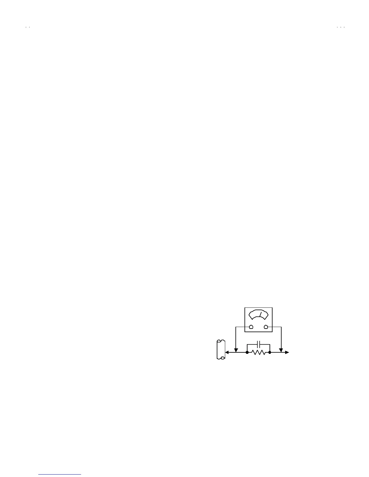
" Alte rnate Che ck Met hod
Plug th e A C line c ord d irect ly into th e A C ou tlet (d o n ot use a lin e
isolatio n tr an sformer dur ing t his che ck.). Use an AC vo lt me ter
h aving 1 00 0 oh ms per volt or m or e sens it ivity in th e fo llowing
mann er. Con nec t a 1 50 0Ω 10W res ist or par a lle le d b y a 0 .1 5µF
AC-type c apa cit or bet ween an expo sed met al pa rt a nd a kno wn
g ood e ar th gro un d (water pipe , etc.). Meas ure th e A C vo lt ag e
across th e res ist or with th e AC voltmeter . M ove th e r esistor
con nec tion to e ach exp ose d metal par t, p art icularly a ny exp osed
metal p art havin g a r etu rn pat h to t he ch assis, an d m easu re th e
AC voltag e ac ross the res ist or. No w, rever se th e plu g in th e AC
ou tlet and re pe at eac h m ea sur emen t. An y volt ag e measu red
must not exc eed 0.7 5V AC (r.m. s.). This c orresponds to 0.5mA
AC (r.m.s.).
Howeve r, in tropical area, this must not exce ed 0.3V AC ( r.m.s.).
This corresponds to 0.2mA AC (r.m.s.).
0.15μF AC-T YPE
1500 Ω 10W
GOOD EARTH GROUND
PLACE THIS PROBE
ON E A C H EX PO SE D
ME T AL PA RT
AC VOLTMETER
(HAVING 1000 Ω /V,
OR MOR E SENSIT IVITY)
 Loading...