31
REPLACEMENT OF CHIP COMPONENT
!
CAUT IONS
1. Avoid heating for more than 3 seconds.
2. Do n ot rub t he elect rodes an d t he resist p arts of th e p att ern.
3. W hen rem oving a c hip part, m elt th e s older ad equ ately.
4. Do n ot reuse a ch ip p ar t afte r re mo ving it .
!
SOLDERING IRON
1. Use a hig h ins ulatio n s older ing iron with a t hin po inted e nd of it .
2. A 3 0 w s older ing iron is r ec ommend ed for easily r em oving p arts.
! REPLACEMENT ST EPS
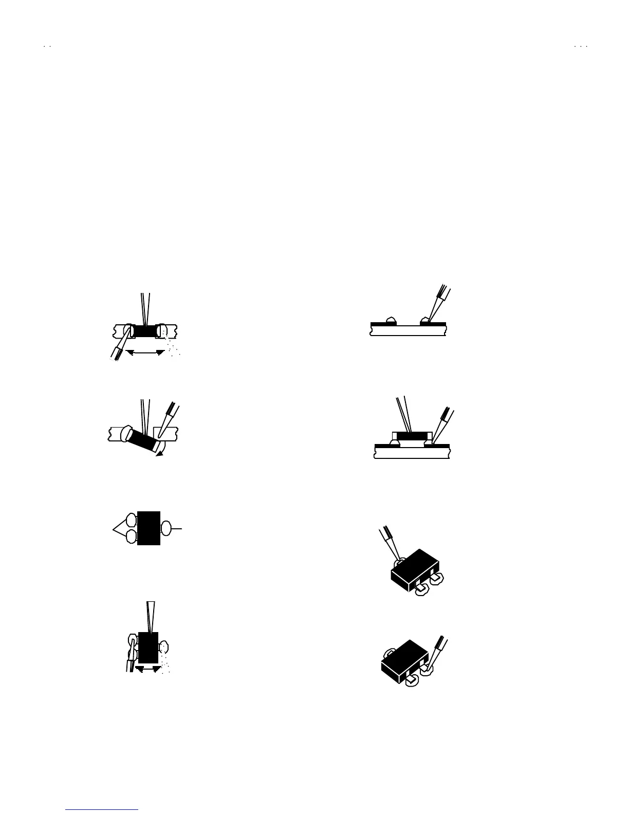
1. How to remove Chip parts
$
$$
$ Resi st ors, ca pa cit ors , et c
(1) As sh own in t he f igure, pu sh th e pa rt with twee zers and
alte rnat ely melt the solde r at each en d.
(2) Sh if t with tweeze rs an d remo ve th e ch ip p art.
$
$$
$ Trans istors, diodes , va ria bl e r es istor s, et c
(1) Ap ply e xt ra so lder to ea ch le ad .
(2) As sh own in t he f igure, pu sh th e pa rt with twee zers and
alte rnat ely melt th e sold er a t each le ad . S hift an d rem ove t he
chip part.
Note : A fter re movin g t he part, remove remain ing solder from the
pattern.
2. How to install Chip parts
$
$$
$
Resi stors, ca pa cit ors , etc
(1) Apply solder to the pattern as indic ated in the fig ure.
(2) Grasp t he ch ip p art with twee zers and plac e it on th e s old er.
The n h ea t an d melt th e so lder a t both en ds of t he chip part.
$
$$
$ Trans istors, diodes , va ria bl e r es istor s, etc
(1) Apply solder to the pattern as indic ated in the fig ure.
(2) Gr asp th e ch ip p art wit h t weeze rs an d p lace it on th e so lder .
(3) First solder lead
A
as indica ted in the figure.
(4) The n so ld er le ads B and C.
SOLDE R SOLD E R
A
B
C
A
B
C
 Loading...