EasyManua.ls Logo

JVC AV-25MS16/H User Manual

JVC AV-25MS16/H
116 pages
To Next Page IconTo Next Page
Page #1 background imageLoading...
Page #1 background image
SERVICE MANUAL
COPYRIGHT © 2006 Victor Company of Japan, Limited
No.YA445
2006/8
COLOUR TELEVISION
YA44520068
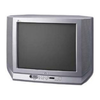
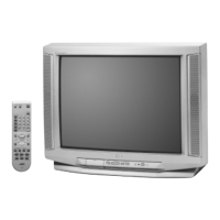
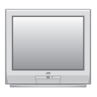
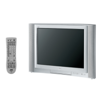
AV-25MS16/H, AV-25MX16/G,
AV-25MX16
/S, AV-25MX56/S
TABLE OF CONTENTS
1 PRECAUTION. . . . . . . . . . . . . . . . . . . . . . . . . . . . . . . . . . . . . . . . . . . . . . . . . . . . . . . . . . . . . . . . . . . . . . . . . 1-3
2 SPECIFIC SERVICE INSTRUCTIONS . . . . . . . . . . . . . . . . . . . . . . . . . . . . . . . . . . . . . . . . . . . . . . . . . . . . . . 1-4
3 DISASSEMBLY . . . . . . . . . . . . . . . . . . . . . . . . . . . . . . . . . . . . . . . . . . . . . . . . . . . . . . . . . . . . . . . . . . . . . . . 1-6
4 ADJUSTMENT . . . . . . . . . . . . . . . . . . . . . . . . . . . . . . . . . . . . . . . . . . . . . . . . . . . . . . . . . . . . . . . . . . . . . . . 1-12
5 TROUBLESHOOTING . . . . . . . . . . . . . . . . . . . . . . . . . . . . . . . . . . . . . . . . . . . . . . . . . . . . . . . . . . . . . . . . . 1-33
BASIC CHASSIS
CW3

Table of Contents

Questions and Answers:

JVC AV-25MS16/H Specifications

General IconGeneral
Screen Size25 inches
Display TechnologyCRT
Aspect Ratio4:3
Audio Output ModeStereo
Speakers2
InputsComposite, S-Video

Summary

SECTION 1 PRECAUTION

1.1 SAFETY PRECAUTIONS

Essential safety guidelines for handling and repairing the television.

SECTION 2 SPECIFIC SERVICE INSTRUCTIONS

2.1 FEATURES

Overview of special features and functions of the television models.

2.2 MAIN DIFFERENCE LIST

Table detailing key differences between the television models.

2.3 REMOTE CONTROL UNIT

Identification and illustration of the remote control units.

2.4 TECHNINAL INFORMATION

Detailed pin functions for the main MI-COM (CPU) on the main printed circuit board.

SECTION 3 DISASSEMBLY

3.1 DISASSEMBLY PROCEDURE

Step-by-step instructions for disassembling the television unit.

3.2 MEMORY IC REPLACEMENT

Guide for replacing the memory IC, including system constant checks.

SECTION 4 ADJUSTMENT

4.1 ADJUSTMENT PREPARATION

Essential steps and considerations before performing TV adjustments.

4.2 PRESET SETTING BEFORE ADJUSTMENT

Recommended initial settings for various TV functions before adjustment.

4.3 MEASURING INSTRUMENT AND FIXTURES

List of necessary measuring instruments and fixtures for service adjustments.

4.4 ADJUSTMENT ITEMS

Comprehensive list of all adjustable items, categorized by circuit.

4.5 ADJUSTMENT LOCATION

Diagrams showing the physical locations of adjustment points on the main PWB.

4.6 BASIC OPERATION OF SERVICE MODE

Instructions on how to navigate and operate the service mode menus.

4.6.4 SERVICE MODE FLOW CHART

Visual flowchart illustrating the service mode adjustment paths.

4.7 INITIAL SETTING VALUE OF SERVICE MODE

Table of initial setting values for various adjustment items.

4.8 ADJUSTMENT PROCEDURE

Detailed procedures for performing specific adjustments like voltage checks.

4.8.3 FOCUS

Procedure for adjusting the picture focus using the HVT.

4.8.4 DEFLECTION CIRCUIT

Instructions for adjusting various deflection circuit parameters for optimal picture geometry.

4.8.5 VIDEO CIRCUIT

Procedures for adjusting video circuit parameters like white balance and colour.

4.8.6 VSM PRESET SETTING

Guide for setting and adjusting VSM (Video Status Memory) presets.

4.8.7 PURITY AND CONVERGENCE

Detailed steps for adjusting picture purity and convergence for optimal color alignment.

SECTION 5 TROUBLESHOOTING

5.1 SELF CHECK FUNCTIONS

Explanation of the TV's self-check features and how they indicate failures.

Related product manuals