1-20 (No.49787B)
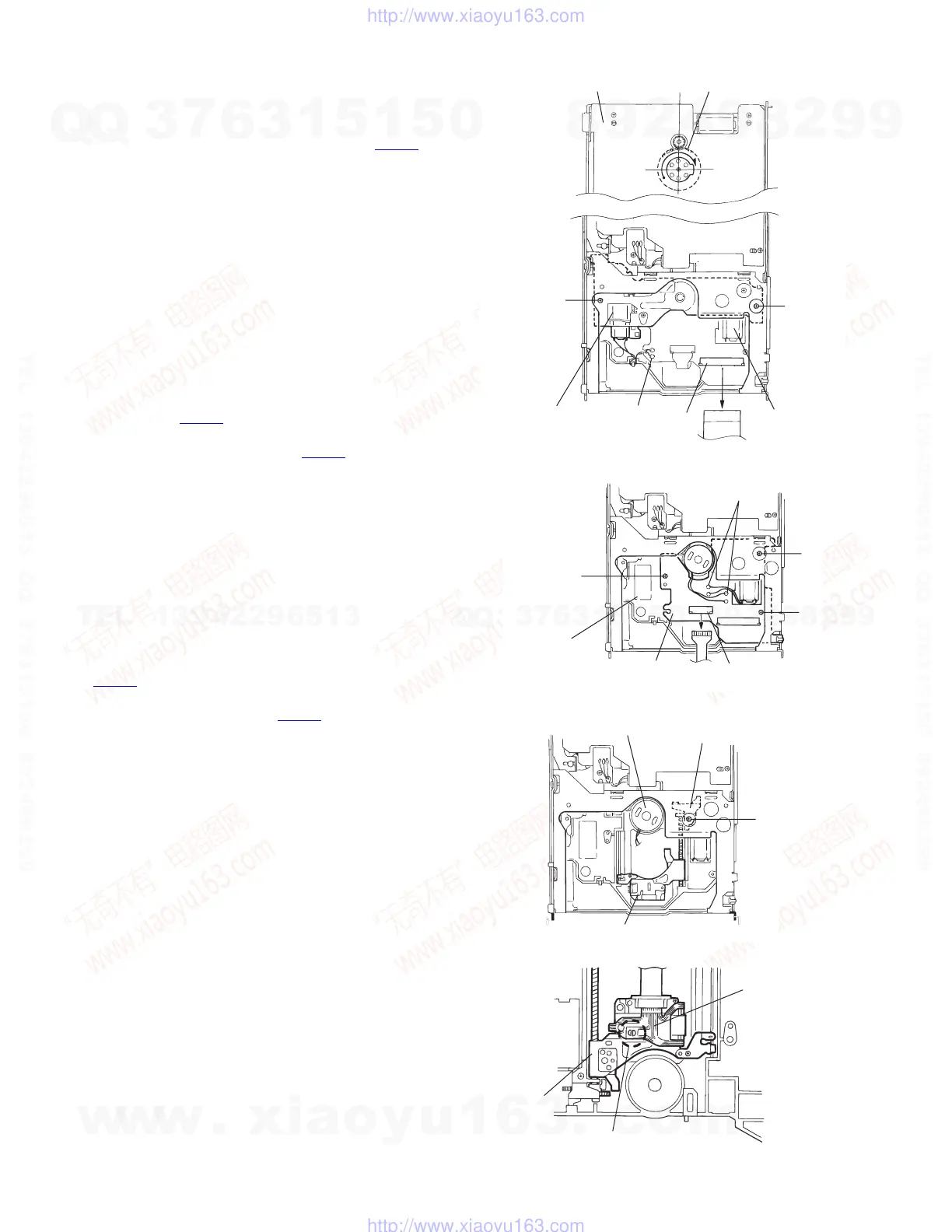
3.2.13.8 Pickup replacement procedure
(See Fig.38 to 44)
(1) Remove the bottom cover, front panel and top cover from
the exterior section.
(2) Unplug the flexible ribbon wire from connector CN502 on
the traverse mechanism PC board assembly.
(3) Turn the rear slider and third gear in the lifter section coun-
terclockwise until the traverse mechanism assembly is in
the lowermost (bottom) position.
(4) Unsolder the two wires (black and brown) connected to the
tray motor.
(5) Remove the two screws M from the round holes on the
chassis (R) assembly to remove the lifter bracket (L).
(6) Remove the lower rod.
(7) Disconnect the two feed motor wires (blue and white), two
spindle motor wires (red and black) and two tray motor
wires (brown and black) that are soldered to the mecha-
nism board.
(8) Short-circuit the grounding point on the mechanism board.
Move the mechanism board without disconnecting the wire
from connector CN501
. Solder the short circuit round on
the pickup assembly.
(9) Disconnect the wire from connector CN501
on the mecha-
nism board.
(10) Remove the three fixing screws N from the round holes on
the chassis (R) assembly to remove the traverse mecha-
nism board assembly.
(11) Remove the pickup shaft holder fixing screw P to remove
the pickup assembly.
CAUTION:
When replacing the pickup, be sure to apply counter-
measures against static electricity (grounding the opera-
tion table, wrist band and soldering iron). To remove it,
first short-circuit the grounding point on the mechanism
board, then lift the mechanism board assembly with
CN501
connected. Next, short-circuit the grounding
point on the pickup main unit, then unplug the pickup
flexible board from connector CN501
.
CAUTION:
When reassembling, perform in the reverse order.
(12) Remove the two rack arm fixing screws Q.
Pull out the feed slide shaft.
Remove the shaft holder fixing screw R.
(13) When mounting the lifter bracket after replacing the pickup,
shift the lifter unit lever approx. 30 mm towards the inside,
then mount the lifter bracket.
Fig.38
Fig.39
Fig.40
Fig.41
Third gear
M
CN502
Unsolder
Lifter bracket (L)
M
Main PCB assembly
Feed moto
assembly
N
N
N
CN501
Tray motor
assembly
Unsolder
Traverse mechanism
board assembly
Grounding point
P
Pickup assembly
Shaft holder
Spindle motor
Short circuit round
(Drounding point)
Pickup
Flexible wire
w
w
w
.
x
i
a
o
y
u
1
6
3
.
c
o
m
Q
Q
3
7
6
3
1
5
1
5
0
9
9
2
8
9
4
2
9
8
T
E
L
1
3
9
4
2
2
9
6
5
1
3
9
9
2
8
9
4
2
9
8
0
5
1
5
1
3
6
7
3
Q
Q
TEL 13942296513 QQ 376315150 892498299
TEL 13942296513 QQ 376315150 892498299
http://www.xiaoyu163.com
http://www.xiaoyu163.com
 Loading...