(No.PA056<Rev.002>) 13
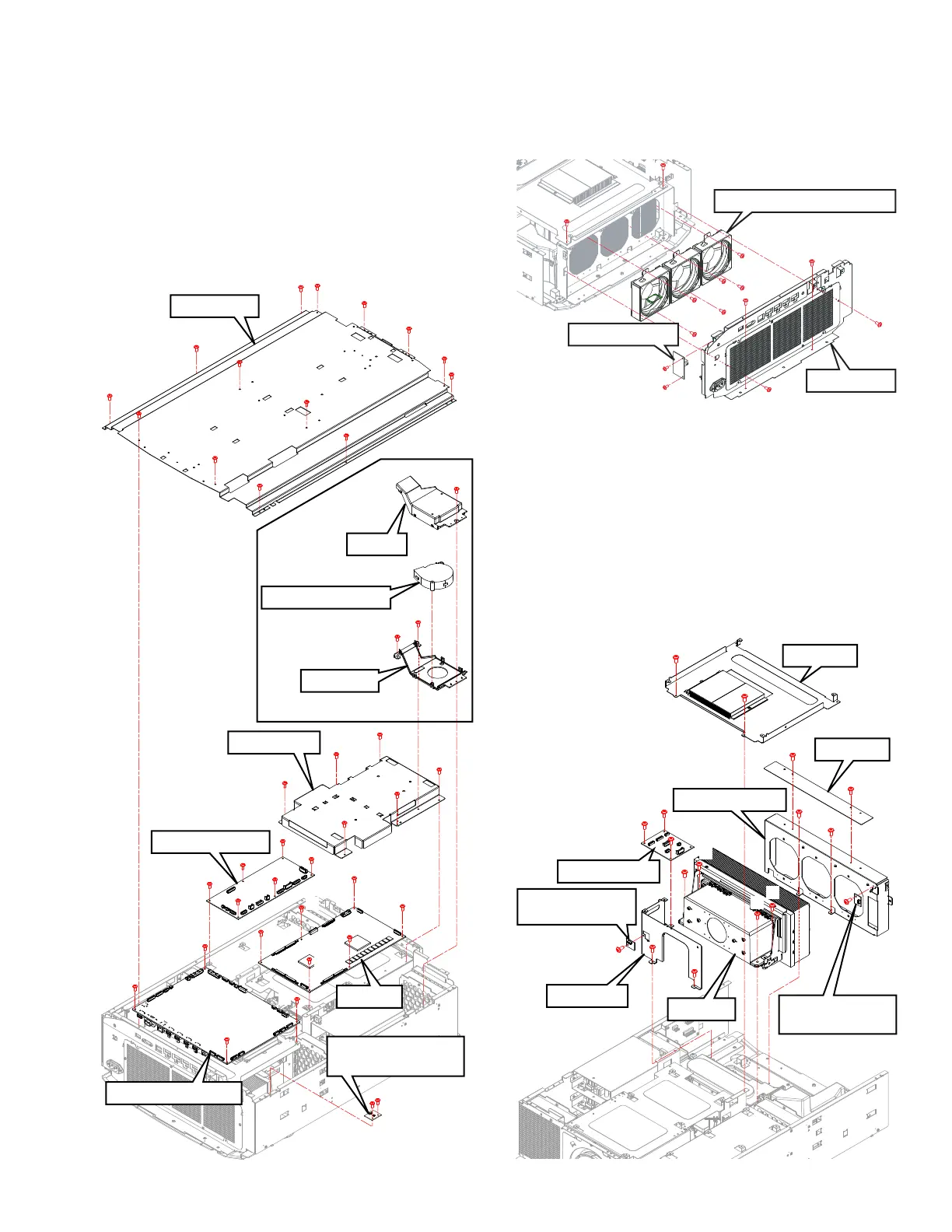
3.2.3 Remove the INTERLOCK PWB, PROCESSOR PWB,
MOTOR PWB and DD PWB (Fig.3-4)
(1) Remove 14 screws (a), and remove the TOP PLATE.
(2) Remove the 2 screws (b), and remove the INTERLOCK
PWB (for the TOP PLATE).
(3) Remove the 4 screws (c), and remove the PROCESSOR
PWB.
(4) Remove the 6 screws (d), and remove the MOTOR PWB.
(5) Remove the 3 screws (e), and remove the DD COOLING
FAN ASSY.
(6) Remove 6 screws (f), and remove the DD SHIELD.
(7) Remove 6 screws (g), and remove the DD PWB.
Fig.3-4
3.2.4 Remove the TERMINAL PWB, LD FAN (Fig.3-5)
(1) Remove 6 screws (a, b, c), and remove the REAR BASE.
(2) Remove the 2 screws (d), and remove the TERMINAL
PWB.
(3) Remove 6 screws (e), and remove the LD FAN.
Fig.3-5
3.2.5 Remove the RELAY 1 PWB, TEMPERATURE SENSOR
PWB and LD UNIT (Fig.3-6)
(1) Remove the 2 screws (a), and remove the BRACKET.
(2) Remove the 3 screws (b), and remove the RELAY 1 PWB.
(3) Remove the 2 screws (c), and remove the BRACKET.
(4) Remove 1 screw (d), and remove the INTERNAL TEM-
PERATURE SENSOR PWB.
(5) Remove the 2 screws (e), and remove the BRACKET.
(6) Remove the 2 screws (f), and remove the FAN BRACKET.
(7) Remove 1 screw (g), and remove the EXTERNAL TEM-
PERATURE SENSOR PWB.
(8) Remove 4 screws (h) and remove the LD UNIT.
Fig.3-6
PROCESSOR PWB
COVER
MOTOR PWB
DD SHIELD
DD PWB
INTERLOCK PWB
(for the TOP PLATE)
TOP PLATE
a
c
c
d
d
d
d
d
d
c
b
b
a
a
a
a
a
a
a
a
a
a
a
a
a
c
g
g
g
g
g
g
e
f
f
f
f
f
f
e
e
DD COOLING FAN
DD COOLING FAN ASSY
BRACKET
a
c
d
d
c
e
e
e
e
e
e
a
b
b
LD FAN1,2,3 (From the left)
REAR BASE
TERMINAL PWB
RELAY 1 PWB
BRACKET
INTERNAL TEMPERATURE
SENSOR PWB
BRACKET
BRACKET
d
b
a
a
b
b
h
g
c
c
h
h
h
LD UNIT
f
e
e
f
FAN BRACKET
EXTERNAL TEMPERATURE
SENSOR PWB
 Loading...