14 (No.PA056<Rev.002>)
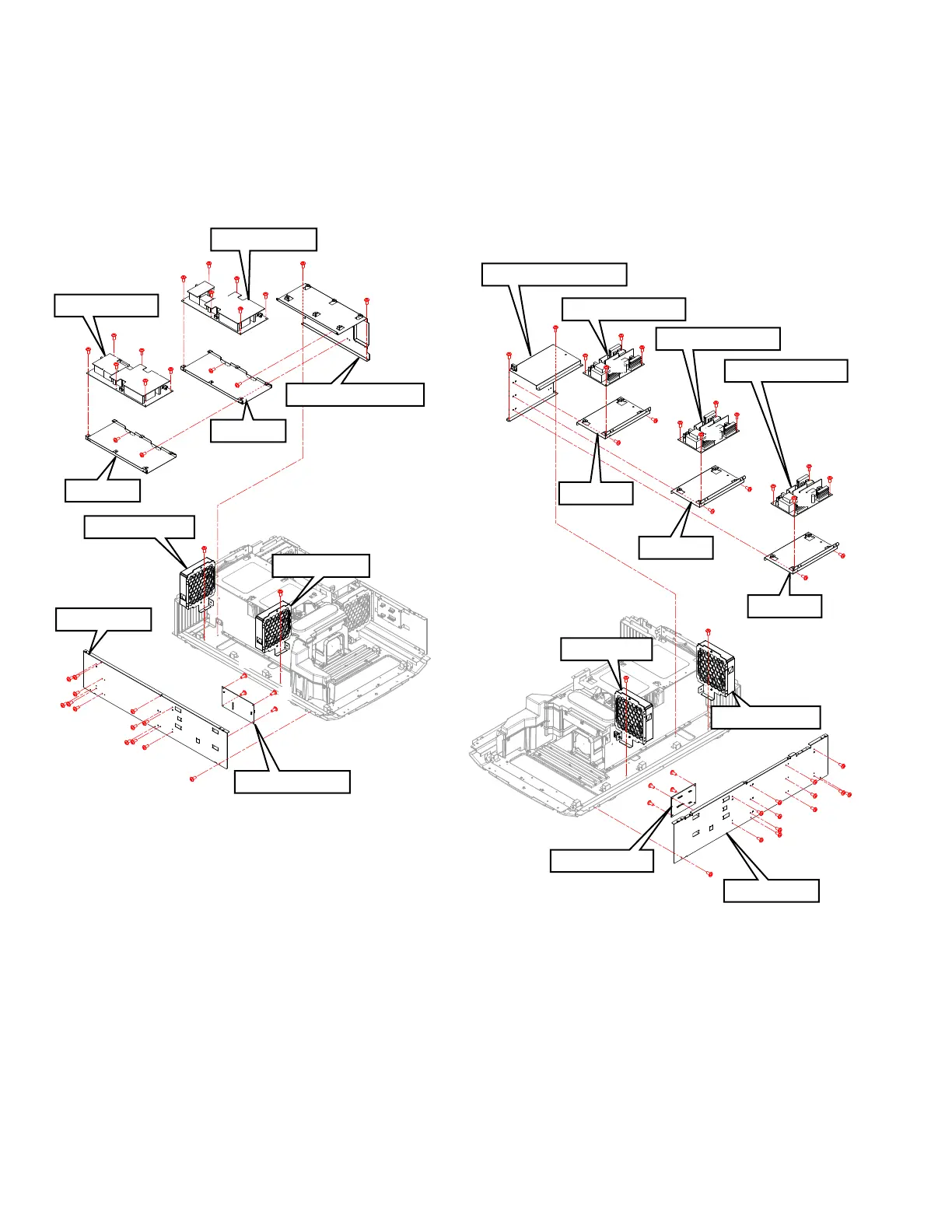
3.2.6 Remove the AC INPUT PWB and POWER PWB (Fig.3-7)
(1) Remove 13 screws (a), and remove the SIDE PLATE.
(2) Remove the 4 screws (b), and remove the AC INPUT PWB.
(3) Remove the 2 screws (c), and remove the INTAKE FAN
and the EXHAUST FAN.
(4) Remove the 2 screws (d), and remove the SHIELDING
COVER.
(5) Remove the 4 screws (e), and remove the BRACKET.
(6) Remove the 12 screws (f), and remove the POWER PWB.
Fig.3-7
3.2.7 Remove the RELAY 2 PWB and LD DRIVER PWB
(Fig.3-8)
(1) Remove 13 screws (a), and remove the SIDE PLATE.
(2) Remove the 4 screws (b), and remove the RELAY 2 PWB.
(3) Remove the 2 screws (c), and remove the INTAKE FAN
and the EXHAUST FAN.
(4) Remove the 2 screws (d), and remove the SHIELDING
COVER.
(5) Remove the 6 screws (e), and remove the BRACKET.
(6) Remove the 12 screws (f), and remove the LD DRIVER
PWB.
Fig.3-8
SIDE PLATE
POWER PWB
POWER PWB
INTAKE FAN
AC INPUT PWB
EXHAUST FAN
SHIELDING COVER
a
a
a
a
a
a
a
b
c
c
d
f
f
f
f
f
f
f
f
e
e
e
e
d
b
a
a
a
a
a
a
b
f
f
f
b
BRACKET
BRACKET
LD DRIVER PWB
SHIELDING COVER
LD DRIVER PWB
LD DRIVER PWB
BRACKET
a
a
a
b
b
b
c
c
d
d
f
f
f
e
e
e
e
e
e
f
f
f
f
f
f
b
a
a
a
a
a
a
a
a
a
a
INTAKE FAN
EXHAUST FAN
SIDE PLATE
RELAY 2 PWB
f
f
f
BRACKET
BRACKET
 Loading...