1-12 (No.MB150)
3.1.9 Removing the micom board
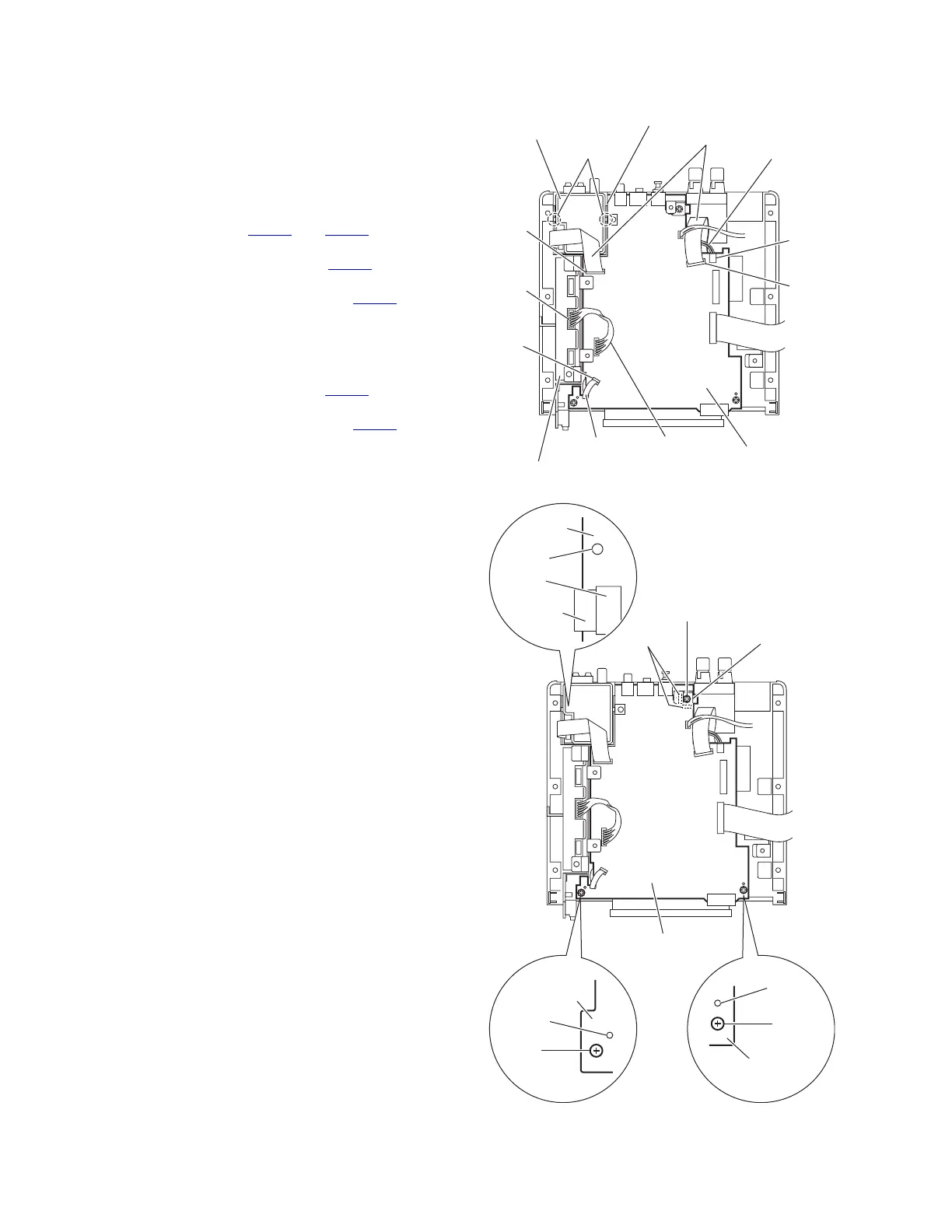
(See Figs.16 and 17)
• Remove the top cover.
• Remove the AL panel L and AL panel R.
• Remove the front panel assembly.
• Remove the rear panel.
• Remove the switching power unit.
• Remove the main board.
(1) From the top side of the main body, disconnect the card
wires from the connectors CN631
and CN701 on the mi-
com board. (See Fig.16.)
(2) Disconnect the wire from the connector CN703
on the mi-
com board. (See Fig.16.)
(3) Disconnect the card wire from the connector CN705
on the
micom board and take out the tuner after releasing the
claws g of the tuner holder. (See Fig.16.)
Reference:
Remove the tuner as required.
(4) Disconnect the wire from the connector CN311
on the dig-
ital amplifier board assembly. (See Fig.16.)
(5) Disconnect the card wire from the connector CN601
on the
main board. (See Fig.17.)
(6) Remove the two screws S and screw S' attaching the mi-
com board. (See Fig.17.)
Reference:
• When attaching the screw S', attach the bracket D with it.
(See Fig.17.)
• When attaching the micom board, attach the screw S and
screw S' after fitting the hole of the main board to the joints
(h,i,j,k) of the main body. (See Fig.17.)
Fig.16
Fig.17
Card wires
Wire
Card wire
CN631
CN703
CN701
CN311
Wire
Tuner
CN705
Joints g
Tuner holder
Digital amplifier board assembly
Micom board
Micom board
Bracket D
Joints h
S'
Micom
board
Joint i
Micom board
Joint j
S
S
Micom board
Joint k
CN601
Card wire
 Loading...