(No.MB150)1-13
3.1.10 Removing the digital amplifier board
(See Figs.18 to 20)
• Remove the top cover.
• Remove the AL panel L and AL panel R.
• Remove the front panel assembly.
• Remove the rear panel.
• Remove the switching power unit.
• Remove the main board.
• Remove the micom board.
(1) From the back side of the main body, disconnect the card
wire from the connector CN313
on the digital amplifier
board assembly. (See Fig.18.)
Reference:
When connecting the wire, connect the wire to connector
CN313
on the digital amplifier board assembly after pass
it through the section m of the side cover L. (See Fig.18.)
(2) From the top side of the main body, remove the two screws
T and two screws U attaching the bracket C. (See Fig.18.)
(3) Take out the bracket C with the headphone board from the
main body.
Reference:
When attaching the bracket C to the bottom chassis, at-
tach it after fitting the hole to the projections n of the bot-
tom chassis. (See Fig.18.)
(4) Take out the digital amplifier board assembly.
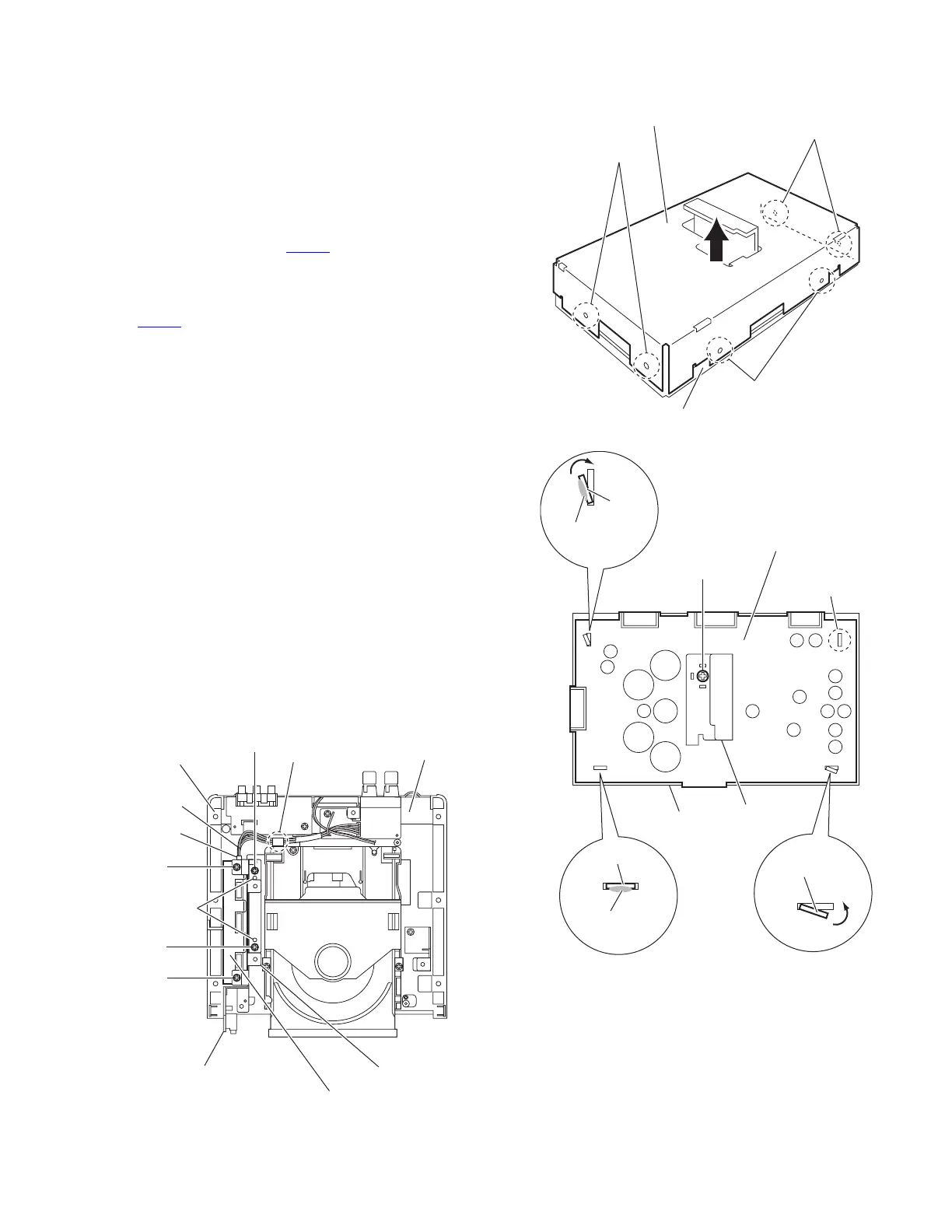
(5) Release the joints (p,q,r) of the deus case A and deus case
B, and remove the deus case A in the direction of the ar-
row. (See Fig.19.)
(6) Remove the screw V attaching the heat sink. (See Fig.20.)
(7) Remove the solder from the soldered sections (s,t) attach-
ing the digital amplifier board to the deus case B and bend
the joints (u,v) in the direction of the arrow. (See Fig.20.)
(8) Take out the digital amplifier board from the deus case B.
Reference:
When attaching the digital amplifier board to the deus case B,
fit the joints (u,v,w,x) of the deus case B to the hole of the dig-
ital amplifier board. (See Fig.20.)
Fig.18
Fig.19
Fig.20
CN313
Wire
m
Side cover L
T
T
U
Digital amplifier board assembly
Bracket C
U
Headphone board
Projections n
Bottom chassis
Joints
p
Joints r
Joints q
Deus case A
Deus case B
V
Digital amplifier board
Heat sink
Solder
section s
Joint u
Joint v
Joint x
Deus case B
Solder
section t
Joint w
 Loading...