EasyManuals Logo
Home>JVC>Speaker System>EX-A1

JVC EX-A1 Service Manual

JVC EX-A1
26 pages
To Next Page IconTo Next Page
To Previous Page IconTo Previous Page
Page #15 background imageLoading...
Page #15 background image
(No.MB150)1-15
3.1.14 Removing the fan motor
(See Figs.21,23 and 24)
Remove the top cover.
Remove the AL panel L and AL panel R.
Remove the rear panel.
Remove the switching power unit.
Remove the main board.
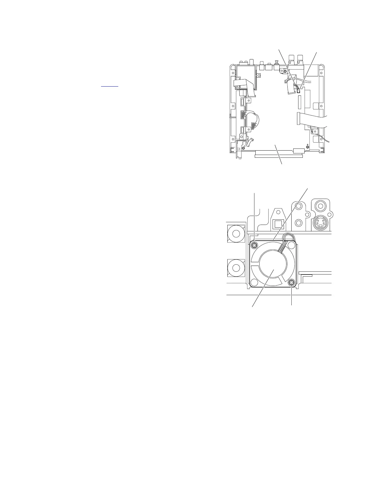
(1) From the top side of the main body, disconnect the wire
from the connector CN703
on the micom board. (See
Fig.23.)
(2) From the back side of the main body, remove the two
screws Z attaching the fan motor to the bracket B. (See
Fig.24.)
(3) Take out the fan motor from the back side of the main body.
Reference:
After attaching the fan motor, fix the wire with the wire holder.
(See Fig.21.)
Fig.23
Fig.24
Wire
CN703
Micom board
Fan motor
Z
Z
Bracket B

Other manuals for JVC EX-A1

Questions and Answers:

Question and Answer IconNeed help?

Do you have a question about the JVC EX-A1 and is the answer not in the manual?

JVC EX-A1 Specifications

General IconGeneral
Speakers2, Real Cherrywood
I/O ports21-pin SCART Out Audio Out (Optical/Subwoofer) Audio In (Analogue) Headphone Out
Output power description2 x 41W
Disc types supportedCD, DVD-R, DVD-RW
Radio Data System (RDS)Yes
Preset stations quantity45
Cassette deckNo
Magnet typeNeodymium
Audio decodersDolby Digital, DTS

Related product manuals