1-14 (No.MB150)
3.1.11 Removing the speaker terminal board
(See Fig.21.)
• Remove the top cover.
• Remove the AL panel L and AL panel R.
• Remove the front panel assembly.
• Remove the rear panel.
• Remove the switching power unit.
• Remove the main board.
• Remove the micom board.
(1) From the back side of the main body, disconnect the wire
from the connector CN313
on the digital amplifier board as-
sembly.
Reference:
When connecting the wire, connect the wire to connector
CN313
on the digital amplifier board assembly after pass
it through the section m of the chassis. (See Fig.18.)
(2) From the top side of the main body, remove the screw W
attaching the speaker terminal board.
Reference:
• When attaching the speaker terminal board, attach the
screw W after fitting the hole of the speaker terminal board
to the joint y of the side cover R.
• After attaching the speaker terminal board, fix the wire and
fan motor wire with the wire holder.
3.1.12 Removing the component video terminal board
(See Fig.21)
• Remove the top cover.
• Remove the AL panel L and AL panel R.
• Remove the front panel assembly.
• Remove the rear panel.
• Remove the switching power unit.
• Remove the main board.
• Remove the micom board.
(1) From the top side of the main body, remove the screw X at-
taching the component video terminal board.
Reference:
When attaching the component video terminal board, at-
tach the screw X after fitting the hole of the component
video terminal board to the joint z of the side cover L.
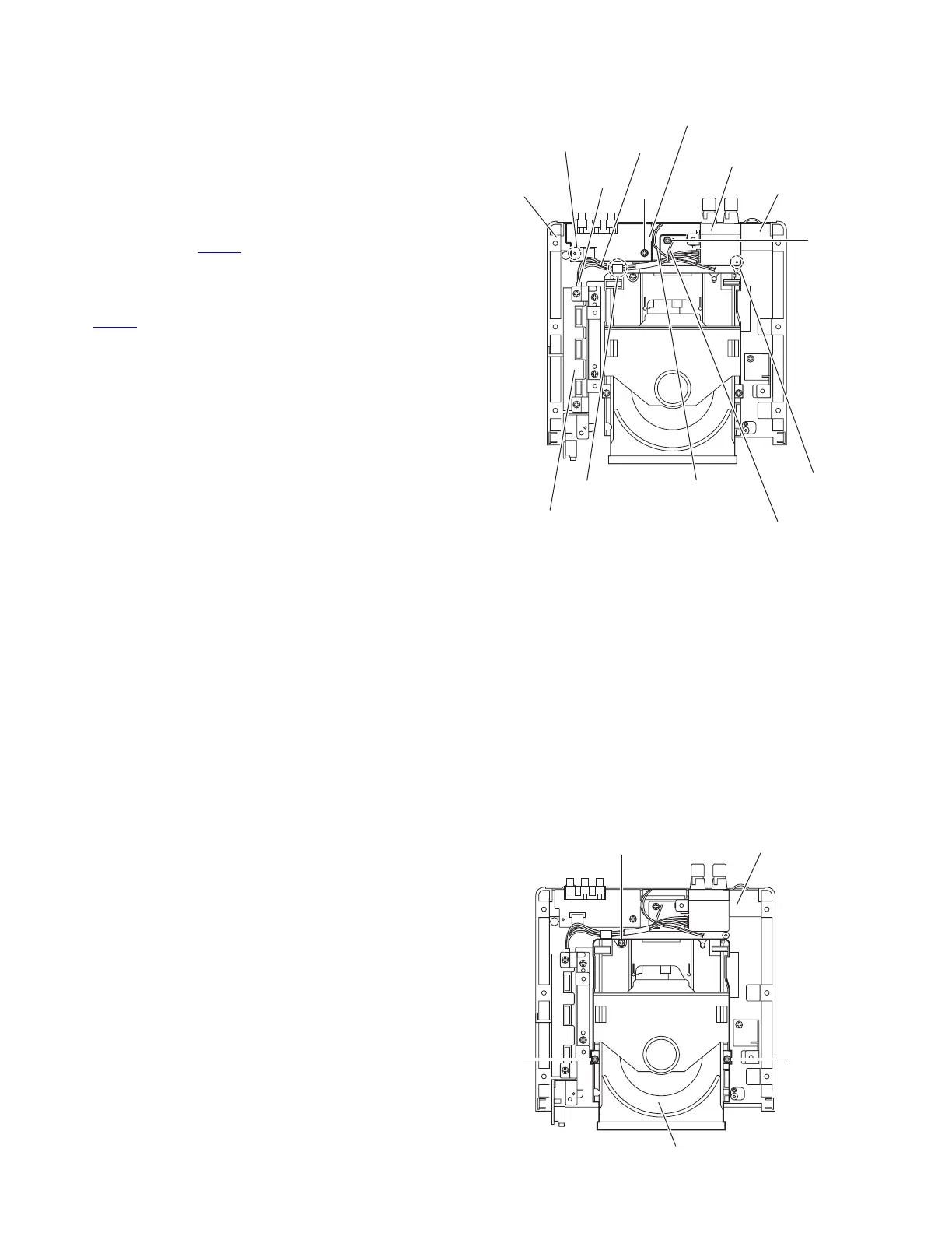
Fig.21
3.1.13 Removing the DVD mechanism assembly
(See Fig.22.)
• Remove the top cover.
• Remove the AL panel L and AL panel R.
• Remove the front panel assembly.
• Remove the rear panel.
• Remove the switching power unit.
• Remove the main board.
• Remove the micom board.
(1) From the top side of the main body, remove the three
screws Y attaching the DVD mechanism assembly.
(2) Take out the DVD mechanism assembly from the bottom
chassis.
Fig.22
W
Side cover R
X
Side cover L
Digital amplifier board assembly
Joint z
Speaker terminal board
Joint y
Wire holder
Fan motor wire
m
Component video terminal board
CN313
Wire
Y
DVD mechanism assembly
Y
Bottom chassis
 Loading...