EasyManuals Logo
Home>JVC>Speaker System>EX-A10

JVC EX-A10 Service Manual

JVC EX-A10
105 pages
To Next Page IconTo Next Page
To Previous Page IconTo Previous Page
Page #11 background imageLoading...
Page #11 background image
(No.MB487)1-11
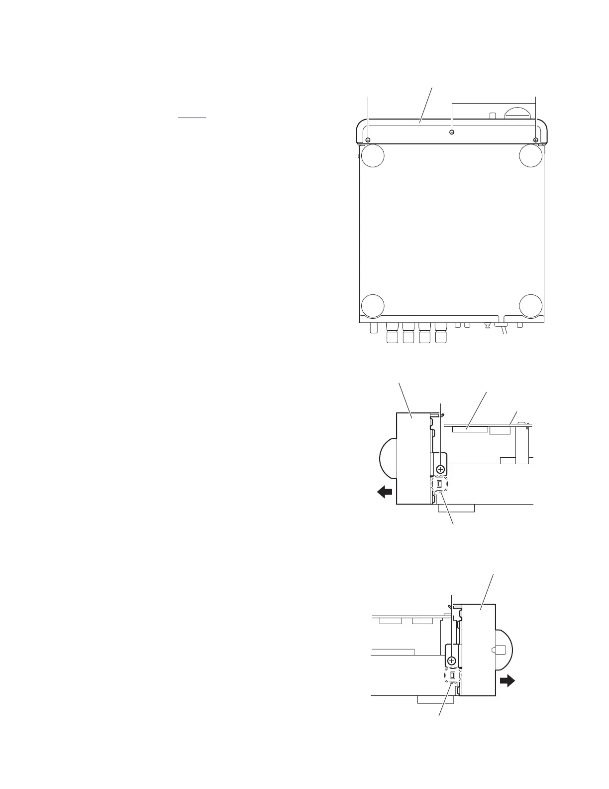
3.1.2 Removing the front panel assembly
(See Figs.4 to 6)
Remove the metal cover.
(1) From the bottom side of the main body, remove the three
screws C attaching the front panel assembly. (See Fig.4.)
(2) From the right side of the main body, disconnect the card
wire from the connector CN703
on the main board. (See
Fig.5.)
(3) From the both sides of the main body, remove the two
screws D attaching the front panel assembly. (See Figs.5
and 6.)
(4) Remove the joints a attaching the front panel assembly and
remove the front panel assembly in the direction of the ar-
row. (See Figs.5 and 6.)
Fig.4
Fig.5
Fig.6
Front panel assembly
C C
Front panel assembly
CN703
Main board
D
a
Front panel assembly
D
a

Table of Contents

Other manuals for JVC EX-A10

Questions and Answers:

Question and Answer IconNeed help?

Do you have a question about the JVC EX-A10 and is the answer not in the manual?

JVC EX-A10 Specifications

General IconGeneral
Impedance6 Ω
RMS rated power20 W
EqualizerYes
Volume controlDigital
Supported radio bandsAM, FM
TypeHome audio micro system
Speakers2-Way, Bass-Reflex
Dimensions (WxDxH)245 x 80 x 297 mm
USB 2.0 ports quantity1
Weight and Dimensions IconWeight and Dimensions
Weight2700 g
Center speaker weight3500 g
Center speaker dimensions (WxDxH)143 x 243 x 257 mm

Related product manuals