1-12 (No.MB487)
3.1.3 Removing the rear panel
(See Fig.7.)
• Remove the metal cover.
(1) From the back side of the main body, remove the twelve
screws E attaching the rear panel.
(2) Remove the joints (b, c) attaching the rear panel to the
main body.
Fig.7
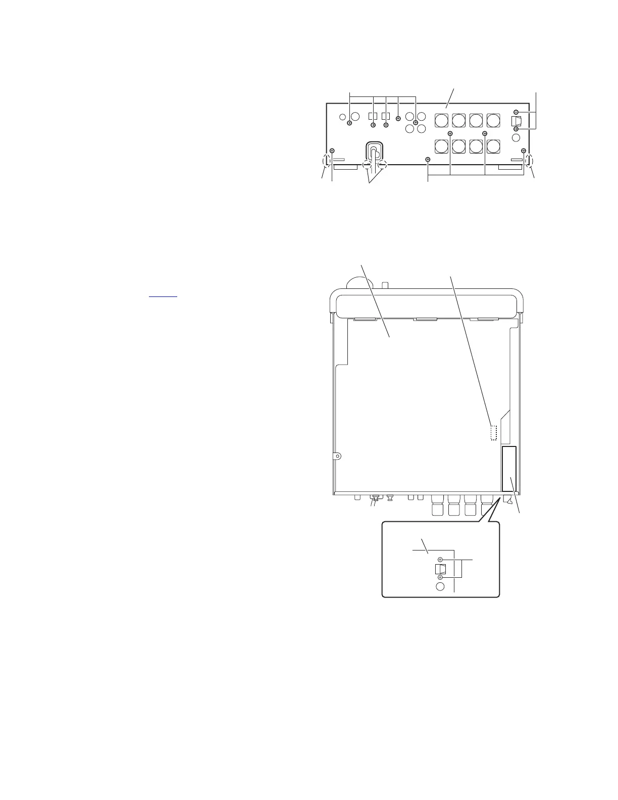
3.1.4 Removing the tuner
(See Fig.8)
• Remove the metal cover.
(1) From the back side of the main body, remove the two
screws F attaching the tuner to the rear panel.
(2) From the top side of the main body, disconnect the card
wire from the connector CN702
on the main board.
(3) Take out the tuner from the main body.
Fig.8
Rear panel
EE
E
E
b
c
b
CN702
Tune
Main board
Rear panel
F
 Loading...