1-10 (No.MB399)
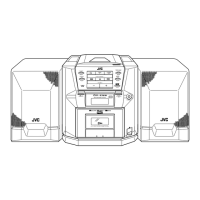
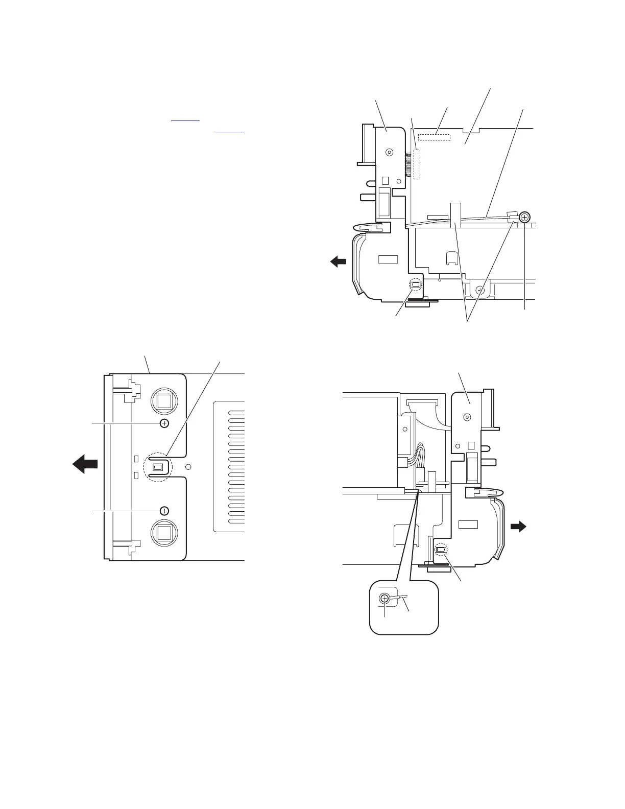
3.1.3 Removing the front panel assembly
(See Figs.7 to 9)
• Remove the side panels L/R and top panel assembly.
(1) From the bottom side of the main body, remove the two
screws H attaching the front panel assembly. (See Fig.7.)
(2) From the forward side of the micom board, disconnect the
card wire from the connector CN426
. (See Fig.8.)
(3) Disconnect the wire from the connector CN501 on the mi-
com board. (See Fig.8.)
(4) From the right side of the main body, remove the screw J
and remove the earth wire. (See Fig.8.)
Reference:
• When attaching the screw J, attach the earth wire with
it. (See Fig.8.)
• After attaching the earth wire, fix it with the spacers as
before. (See Fig.8.)
(5) From the left side of the main body, remove the screw K
and remove the earth wire. (See Fig.9.)
Reference:
When attaching the screw K, attach the earth wire with
it. (See Fig.9.)
(6) From the bottom and both sides of the main body, release
the joints (d, e) of the front panel assembly and remove the
front panel assembly in the direction of the arrow. (See
Figs.7 to 9.)
Fig.7
Fig.8
Fig.9
Front panel assembly
d
H
H
Front panel assembly
CN426
CN501
e
Micom board
Earth wire
J
Spacers
Front panel assembly
e
K
Earth wire
 Loading...