(No.MB399)1-9
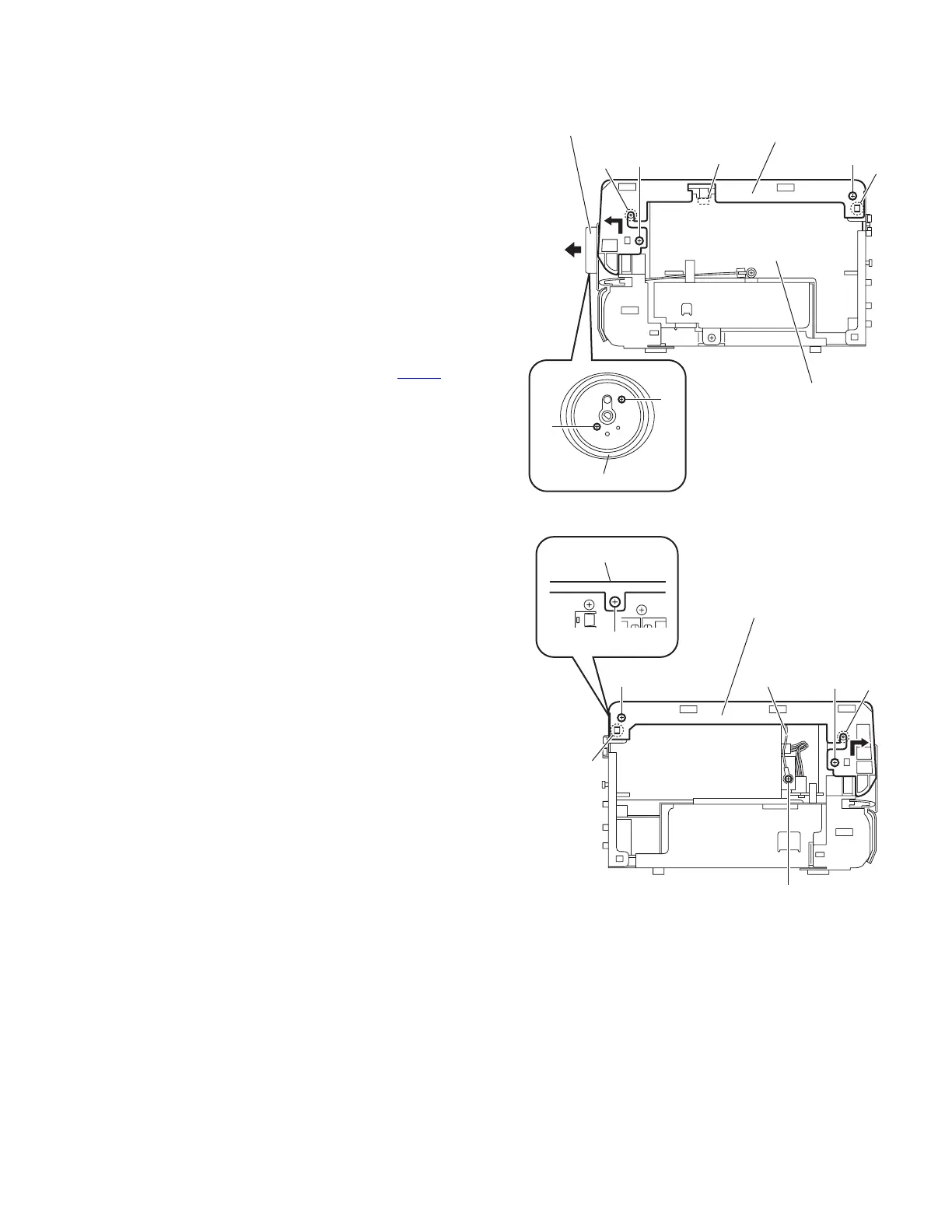
3.1.2 Removing the top panel assembly
(See Figs.5 to 6)
• Remove the side panels L/R.
(1) From the front side of the main body, pull out the volume
knob assembly in the direction of the arrow. (See Fig.5.)
(2) Remove the two screws C and remove the volume orna-
ment. (See Fig.5.)
(3) From the both sides of the main body, remove the two
screws D, two screws E and screw F. (See Figs.5 and 6)
Reference:
When attaching the screw F, attach the earth wire with it.
(See Fig.6.)
(4) From the back side of the main body, remove the screw G
attaching the top panel assembly. (See Fig.6.)
(5) From the both sides of the main body, release the joints b
and remove the joints c in the direction of the arrow. (See
Figs.5 and 6.)
(6) Disconnect the card wire from the connector CN427
on the
micom board while lifting the top panel assembly. (See
Fig.5.)
Fig.5
Fig.6
Top panel assembly
CN427
c
Micom board
Volume ornament
C
C
D
E
b
Volume knob assembly
Top panel assembly
c
D
E
b
Top panel assembly
G
F
Earth wire