(No.MB399)1-17
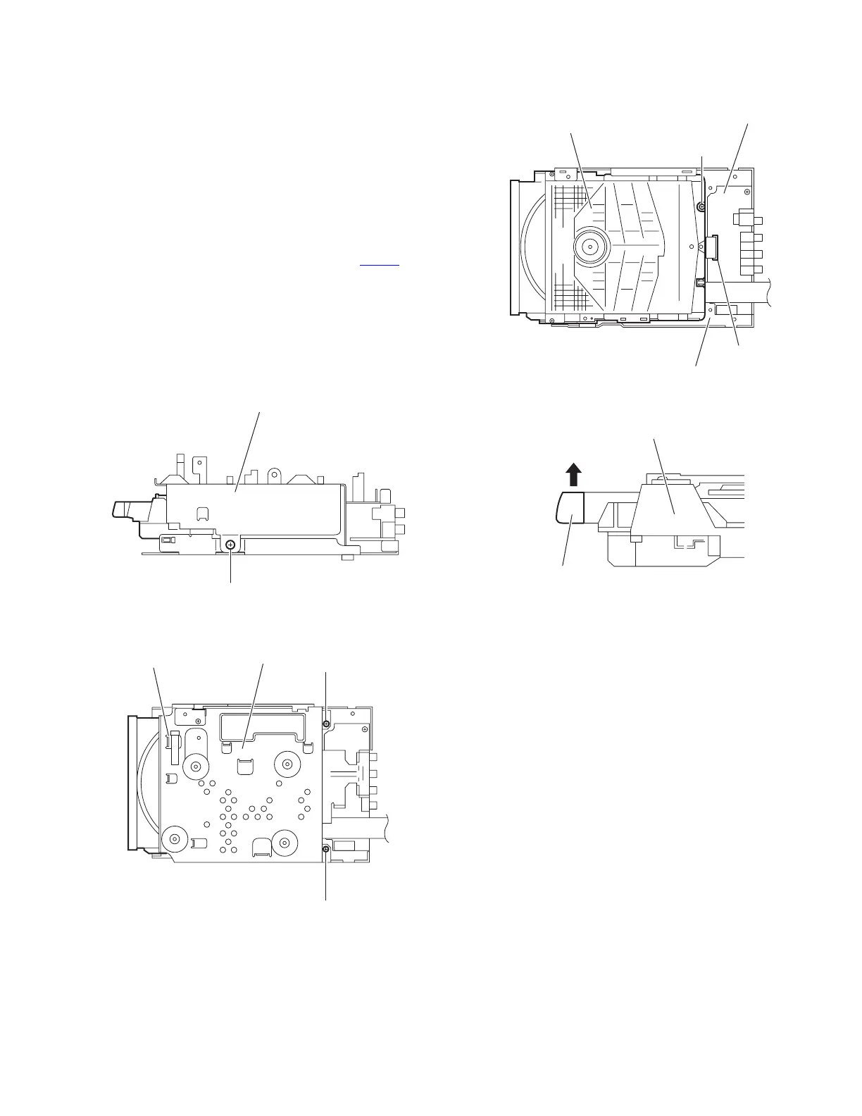
3.1.12 Removing the DVD mechanism assembly
(See Figs.25 to 28)
• Remove the side panels L/R, top panel assembly, front panel
assembly, tuner, rear panel, switching power supply, digital
amplifier board assembly, micom board and regulator board.
(1) From the right side of the main body, remove the screw W
attaching the metal chassis. (See Fig.25.)
(2) From the top side of the main body, remove the two screws
X and take out the metal chassis. (See Fig.26.)
Reference:
When attaching the metal chassis, pass the card wire
through the hole t on the metal chassis as before.
(3) Disconnect the card wire from the connector CN703
on the
video board. (See Fig.27.)
(4) Remove the screw Y and take out the DVD mechanism as-
sembly from the bottom chassis. (See Fig.27.)
Reference:
When the resolution of DVD mechanism assembly is done se-
quentially, remove a CD fitting in the direction of the arrow.
(See Fig.28.)
Fig.25
Fig.26
Fig.27
Fig.28
Metal chassis
W
Metal chassis
t
X
X
DVD mechanism assembly
Video board
CN703
Bottom chassis
Y
DVD mechanism assembly
CD fitting
 Loading...