1-18 (No.MB399)
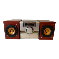
3.1.13 Removing the switch board
(See Fig.29)
• Remove the side panels L/R and top panel assembly.
From the inside of the top panel assembly, remove the three
screws Z and take out the switch board.
Fig.29
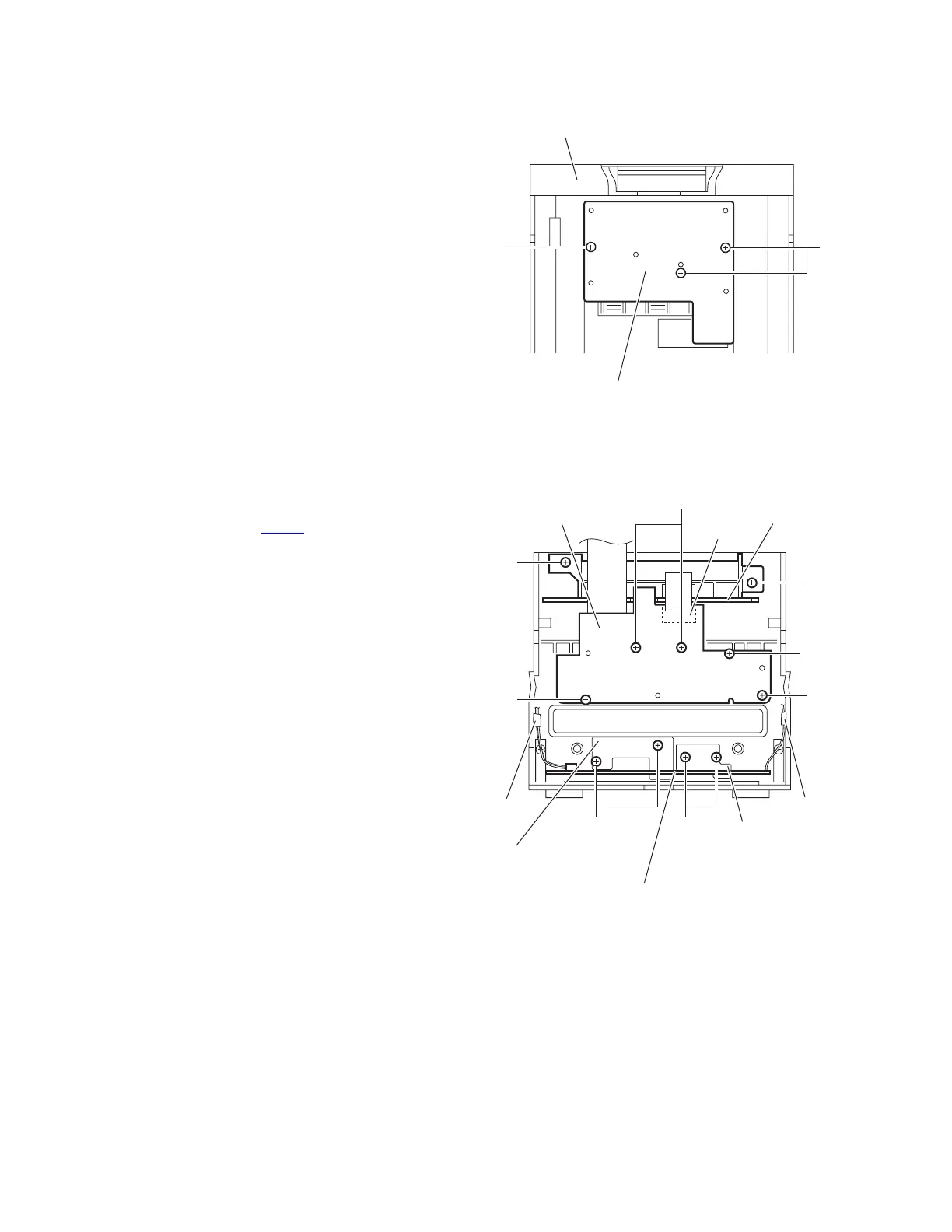
3.1.14 Removing the front board
(See Fig.30)
• Remove the side panels L/R, top panel and front panel assem-
blies.
(1) From the inside of the front panel assembly, disconnect the
card wire from the connector CN605
on the front board.
(2) Remove the five screws AA and take out the front board.
3.1.15 Removing the FL board
(See Fig.30)
• Remove the side panels L/R, top panel assembly, front panel
assembly and front board.
Remove the two screws AA and take out the FL board.
3.1.16 Removing the headphone and USB board
(See Fig.30)
• Remove the side panels L/R, top panel and front panel assem-
blies.
(1) Remove the four screws AA and take out the support
boards.
(2) Take out the headphone and USB board.
Reference:
After attaching the headphone and USB board, fix the wires
with the spacers as before.
Fig.30
Top panel assembly
Switch board
Z
Z
Front board
FL board
CN605
AA
AA
AA
AA
AA
AA
Headphone and USB board
Support board
AA
Support board
Spacer
Spacer
 Loading...