2-32
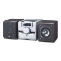
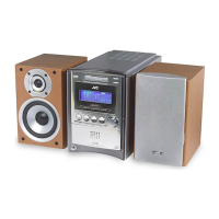
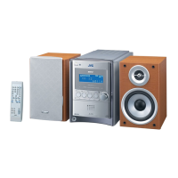
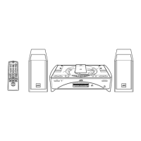
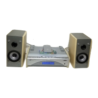
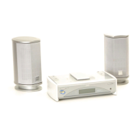
UX-G6/FS-G6
Disassembly method
(TD-UXG6)
Removing the top cover (See Fig.1)
1. Remove the two screws A and the four screws B
attaching the top cover.
2. Remove the top cover from behind in the direc-
tion of the arrow while pulling the sides outward.
Removing the front panel assembly
(See Fig.2 to 5)
• Prior to performing the following procedure,
remove the top cover.
1. Disconnect the card wire from connector CN637
on the main board and remove the screw C
attaching the ground terminal on the main board.
2. Remove the three screws D on the bottom of the
body.
3. Release the joint "a" on the bottom and the joints
"b" on both sides of the body, and remove the
front panel assembly toward the front.
Fig. 1
Fig. 2
Fig. 3
Fig. 4Fig. 5
A x 2
B
B
B
Top cover
Front panel assembly
Main board
CN637
C
Front panel assembly
D
D
D
Joint a
Front panel assembly
Joint b
Joint b
 Loading...