2-33
UX-G6/FS-G6
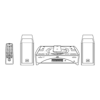
Removing the rear panel
(See Fig.6 and 7)
• Prior to performing the following procedure,
remove the top cover.
1. Remove the three screws E attaching the rear
panel on the back of the body and release the
two joints "c" on both sides while moving the rear
panel upward
2. Disconnect the harness from connector CN633
on the main board.
(When disconnecting the harness from the rear
panel, unhook the upper and lower four hooks of
the wire stopper on the back of the rear panel
and pull out the harness outward.)
Removing the cassette mechanism
assembly (See Fig.8)
• Prior to performing the following procedure,
remove the top cover and the front assembly.
1. Disconnect the card wire from connector CN647
and the harness from CN635 on the main board
respectively.
2. Disconnect the harness from the connector on
the motor board in the cassette mechanism
assembly.
3. Remove the four screws F and detach the
cassette mechanism assembly upward.
Fig. 6
Fig. 7
Fig. 8
Fig.7-1
CAUTION: Lift the lock and
pull out the wire.
E
E
Joint c
Rear panel
Joint c
CN633
Main
board
Wire stopper
Rear panel
CN633
Fig. 7Fig. 7
F
F
CN647
F
Main
board
CN635
Cassette mechanism assembly
Connector on the
motor
board
 Loading...