1-10 (No.MB004)
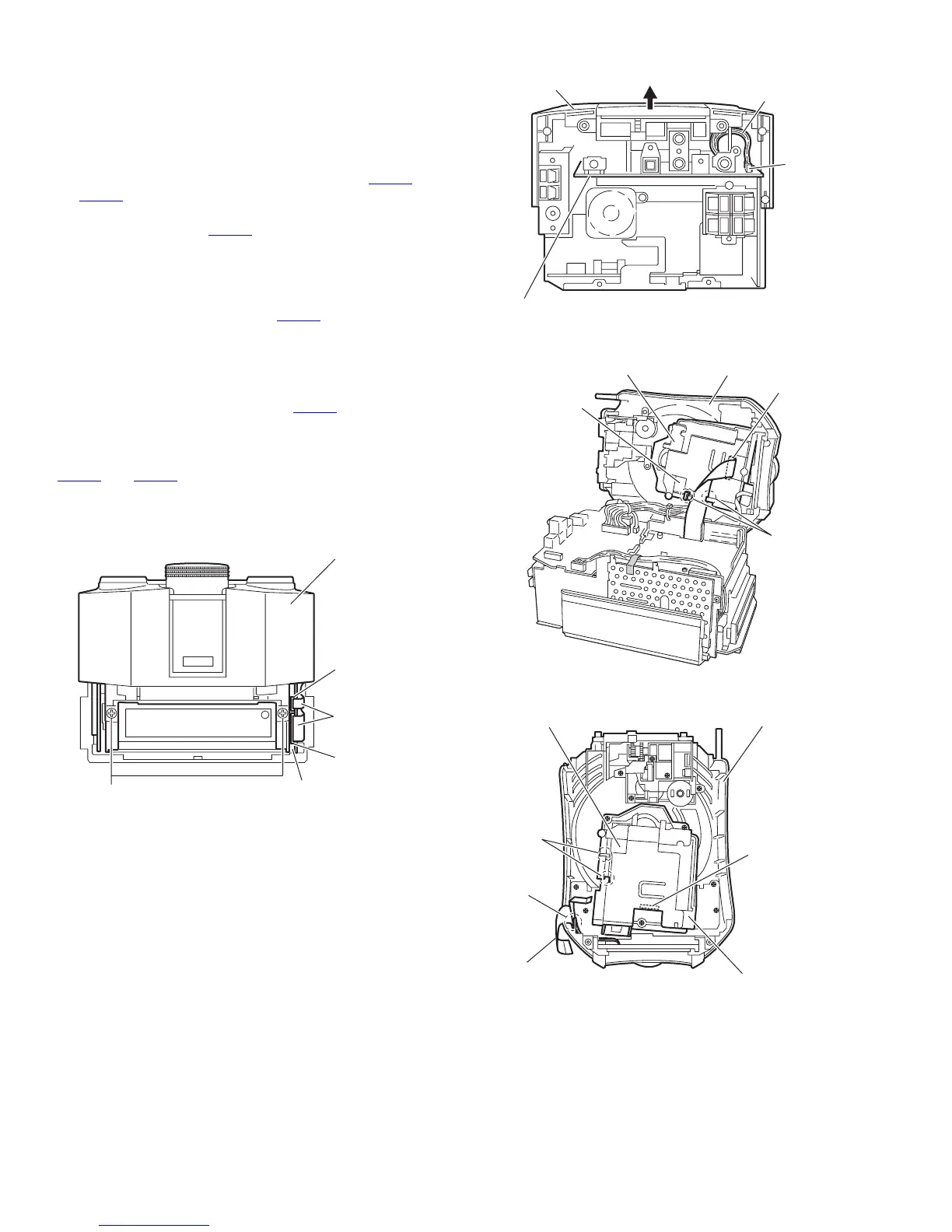
3.1.4 Removing the top case assembly
(See Figs.4 to 7)
• Prior to performing the following procedures, remove the rear
cover and bottom case (B).
(1) From the front side of the main body, remove the two
screws F attaching the top case assembly. (See Fig.4.)
(2) Disconnect the card wires from the connectors CN721
and
CN741 on the micon board. (See Fig.4.)
(3) From the back side of the main body, disconnect the wire
from the connector CN451
on the function board. (See
Fig.5.)
(4) Remove the top case assembly while lifting it in the direc-
tion of the arrow. (See Fig.5.)
(5) From the inside of the top case assembly, disconnect the
card wire from the connector CN651
on the CD servo
board. (See Figs.6 and 7.)
Reference :
Reassembly of the top case assembly.
• Before reattaching the top case assembly to the main body,
connect the card wire to the connector CN651
on the CD servo
board and hang it to the holder section c of the CD mechanism
assembly. (See Figs. 6 and 7)
• Let the card wire to be connected across the connectors
CN721
and CN741 go through the slit d on the top case as-
sembly. (See Fig. 7.)
Fig.4
Fig.5
Fig.6
Fig.7
F
Top case assembly
CN741
CN721
Card wires
Micon board
CN451
Wire
Top case asembly
Function board
CN651
CD mechanism assembly
CD servo board
Holder
section
c
Top case assembly
CN651
Notch d
Card wire
CD mechanism assembly
CD servo board
Holder
section c
Top case assembly
 Loading...