(No.MB004)1-11
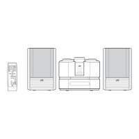
3.1.5 Removing the tuner
(See Fig.8)
• Prior to performing the following procedures, remove the rear
cover, bottom case (B) and top case assembly.
(1) From the right side of the main body, disconnect the card
wire from the connector CN1
on the tuner.
Fig.8
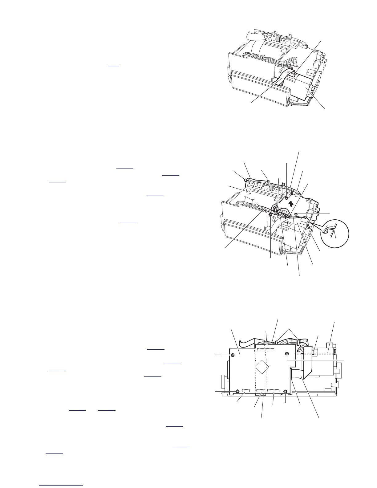
3.1.6 Removing the function board
(See Fig.9)
• Prior to performing the following procedures, remove the rear
cover, bottom case (B) and top case assembly.
(1) From the top side of the main body, disconnect the fan mo-
tor wire from the connector CN942
on the function board.
(2) Disconnect the wires from the connectors CN893
and
CN895 on the function board.
(3) Remove the spacer and tie band fixing the wires.
(4) Disconnect the wire from the connector CN301
on the dig-
ital amplifier board.
(5) Remove the three screws G attaching the function board.
(6) Lift the function board in the direction of the arrow and dis-
connect it from the connector CN951
on the digital amplifier
board.
Reference :
When connecting the fan motor wire, put it through the slit e of
the function board.
Fig.9
3.1.7 Removing the micon board
(See Fig.10)
• Prior to performing the following procedures, remove the rear
cover, bottom case (A), bottom case (B) and top case assem-
bly.
(1) From the right side of the main body, remove the tie bands
bundling the wires.
(2) Disconnect the wire from the connector CN805
on the mi-
con board.
(3) Disconnect the card wires from the connectors CN661
and
CN871 on the micon board.
(4) Disconnect the wire from the connector CN893
on the func-
tion board.
(5) Remove the two screws H and two screws J attaching the
micon board.
(6) Pull the micon board toward this side, disconnect the con-
nectors CN801
and CN802 on the micon board.
Reference :
• After connecting the card wire to the connector CN661
on
the micon board, bend it as was done before disassembly
and insert it inside the center chassis.
• After connecting the wires to the connectors (CN805
,
CN893
) on the micon and function boards, bundle the wires
with the tie bands.
Fig.10
Tune
Card wire
CN1
G
CN895
G
G
CN893
Function board
CN942
Spacer
Wire
Digital amplifier
board
CN301
Wire
Fan motor
Fan motor wire
Tie band
CN951
Slit e
J
J
Micon board
CN893
H
CN871
CN802
CN661
CN801
H
CN805
Card wire
Card wire
Fanction board
Wire
Tie bands
 Loading...