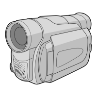
Do you have a question about the JVC GR-DA30UC and is the answer not in the manual?
Explains component units, voltage, signal paths, and connector indications for diagrams.
Details foil/component sides, location guides, and part identification conventions.
Shows connections of the MAIN IF module to other system blocks.
Shows connections of the MAIN CPU module to other system blocks.
Shows connections of the MAIN AUDIO module to other system blocks.
Shows connections of the MAIN PARAGON3 module to other system blocks.
Shows connections of the MAIN PRE/REC module to other system blocks.
Shows connections of the MAIN REG module to other system blocks.
Shows connections of the CCD module to other system blocks.
Shows connections of the POWER UNIT to other system blocks.
Shows connections of the MONITOR module to other system blocks.
Shows connections of the REAR module to other system blocks.
Visual layout of the CCD circuit board, foil and component sides.
Visual layout of the BTU circuit board, foil and component sides.
Visual layout of the Monitor circuit board, foil and component sides.
Visual layout of the Rear circuit board, foil and component sides.
Overview of power distribution and connections between major units.
Overview of the video signal flow and component interactions.
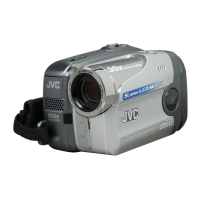
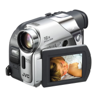
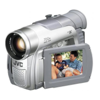
| Type | MiniDV |
|---|---|
| Recording Media | MiniDV tape |
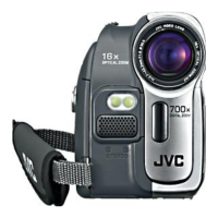
| Optical Zoom | 10x |
| LCD Screen | 2.5 inches |
| Video Resolution | 720 x 480 |
| Image Sensor Size | 1/4 inch |
| Viewfinder | Color |
| Interface | IEEE 1394 (FireWire) |
| Image Sensor | 1/4-inch CCD |
| Battery Life | Approx. 1 hour (with supplied battery) |
| Effective Pixels | 680k |
| Video Format | DV (Digital Video) |
| Dimensions | 94mm |