Do you have a question about the JVC GR-DVL120U and is the answer not in the manual?
| Recording Media | MiniDV |
|---|---|
| Optical Zoom | 10x |
| Digital Zoom | 700x |
| LCD Screen Size | 2.5 inches |
| Weight | 1.2 lbs |
| Image Sensor | CCD |
| Image Sensor Size | 1/4 inch |
| Viewfinder | Color |
| Still Image Format | JPEG |
| Battery Type | Lithium-ion |
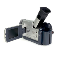
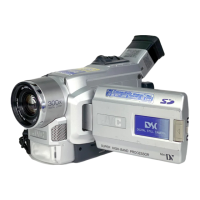
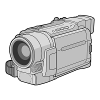
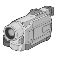
| Type | Digital Camcorder |
| Video Resolution | 720 x 480 |
| Effective Pixels | 680, 000 pixels |
| Video Recording Format | DV (Digital Video) |
| Interface | IEEE 1394 (FireWire) |
Guidelines for safe and compliant servicing procedures.
Confirms insulation resistance between power cord and exposed parts.
Verifies dielectric strength between power cord and exposed parts.
Ensures specified clearance between terminals and metallic parts.
Measures leakage current between earth ground and exposed parts.
Confirms grounding impedance between earth pin and accessible parts.
Precautions and general notes before disassembling or assembling.
Key safety and handling precautions for service.
Details on part numbering and disassembly flow for components.
Shows connector types and their destinations in wiring tables.
Instructions for safely disconnecting various types of wire connectors.
Lists specific tools and jigs needed for various adjustment procedures.
Illustrates the step-by-step process for disassembling cabinet parts and boards.
Procedure to disassemble and reassemble the monitor assembly for 2.5-inch LCD.
Steps for disassembling and reassembling the monitor hinge assembly.
Instructions for disassembling and assembling the Electronic Viewfinder (E.VF) assembly.
Care and handling precautions for CCD image sensor and optical components.
Steps to remove the CCD board and base assemblies.
Steps to reassemble the CCD base and board assemblies.
Lists service repair parts for the OP Block Assembly.
General notes and precautions for mechanism adjustment and repair.
Key precautions regarding torque, power disconnection, and handling.
Explanation of symbols and procedures in disassembly/reassembly tables.
Lists all necessary jigs and tools for mechanism adjustments and checks.
General procedure and mode entry for mechanism disassembly/assembly.
Describes the six mechanism modes and how to distinguish them.
Flowchart for the configuration and disassembly procedure of the mechanism assembly.
Steps for correctly assembling the slide deck and main deck assemblies.
Instructions for connecting the jig connector cable for compatibility adjustment.
Precautions and required test equipment for electrical adjustments.
Procedure for setting up the equipment for electrical adjustments.