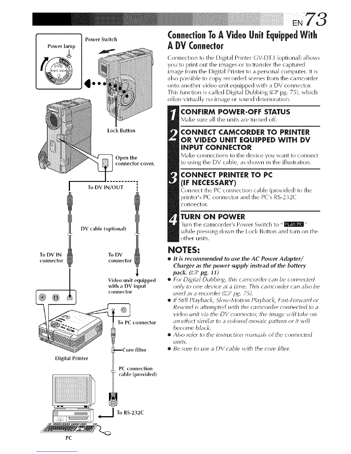
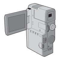
Power SwitcJl
Power lamp
i!i!ii!ii_ii_i!:!i!i!i!i
Loci( Button
Open the
connectorcover.
l •
To DV IN/OUT [
DV cable (optional)
To DV IN
_onneftor
DigltM Printer
To DV
connector
Video unit equipped
with a DV input
connector
To PC connector
--Core filter
PC connection
cable (provkled)
ConnectionToA VideoUnit [quippedWith
A DV Connector
Connection to the Digital Printer GV-DT3 (optional) allows
you to print ()Lit the images or to transfer the captured
image from the Digital Printer to a personal computer. It is
also possible to c(!py recorded scenes fr(im the camcorder
onto another video unit equipped with a DV connector.
This function is called Digital Dubbing (_-7_ pg. 75), which
offers virtually no image or sound deterioration.
CONFIRM POWER-OFF STATUS
M_l<esure_11the unit__re turned off,
CONNECT CAMCORDER TO PRINTER
OR VIDEO UNIT EQUIPPED WITH DV
INPUT CONNECTOR
Make o)nnectJons to the device you want to connect
to using the DV cable, a_ _hown in the illustration.
CONNECT PRINTER TO PC
(IF NECESSARY)
Connect tile P( connection ¢_d_le (provided) to the
printer's P( connector and the P('s R5-2";2(
CORllL_CtOF.
TURN ON POWER
Turn the camcorder's Power Switch to "I'mm_@l-
while pressing down the Lock Button and turn on the
other units.
NOTES:
• It is recommended to use the AC Power Adapter/
Charger as the power supply instead of the battery
pack. (_ / pg. It)
• For Digital Dubbing, &is camcorder carl be conrlected
only t_*one ddvice at a time. This camcorddr carl al_o be
used as a recorddr (_ T_IJg. 7_).
• If Still Playback, Slow-Motion Pbyback, Fast-D_rward or
Rewind is attempted with tile camcorder corlnected to a
video unit via the DV connector, tile image will take on
an effect similar t_>a c_;Iordd mosaic pattern or it will
become black.
• Also refer t_>the instruction marlual_ otthe connected
unit<
• Be 5Urd to use a DVcabld with the c_;re filtdt:
I To RS-232C
t
j
PC