1-13
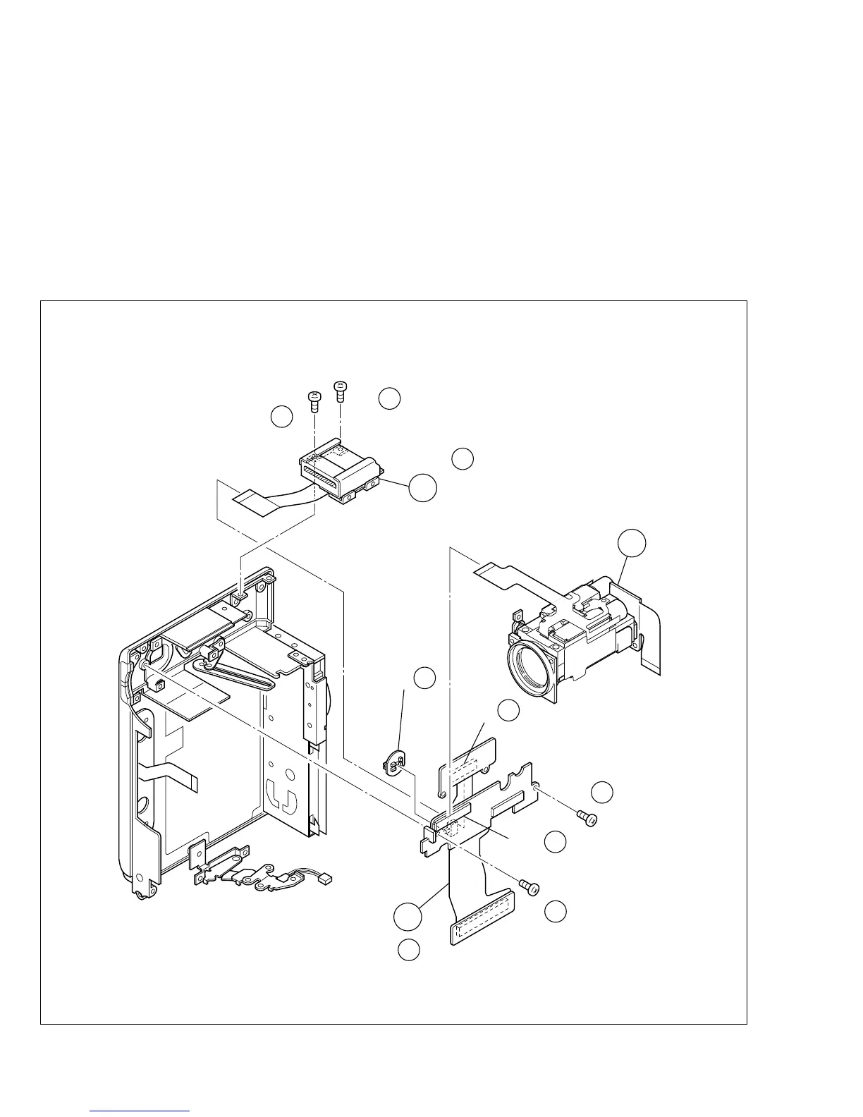
2. See Fig. 1-8-2.
(1) Remove the two screws (44, 45) in order to free the $
OP MDA board assembly.
(2) Remove the two screws (46, 47) and take out the $ OP
MDA board assembly together with the @ OP block as-
sembly and the % shoe assembly.
Note@:
Be careful not to lose the VIDEO and DSC knobs,
which may slip out during the disassembly.
(3) Disconnect the FPCs from the connectors on the @ OP
block assembly and the % shoe assembly.
Fig. 1-8-2
14
12
15
(S b)
44
14
CN
12
NOTE
12
NOTE b
14
NOTE
15
CN
15
(S b)
45
14
(S )
46
15
(S )
47
15
KNOB
(VIDEO
/DSC)