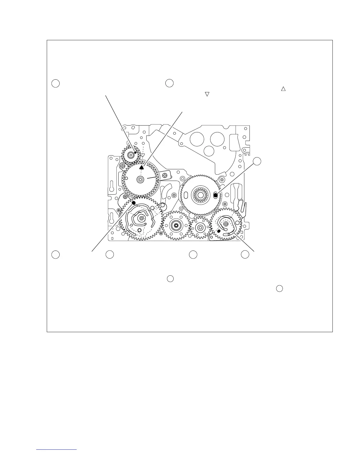
Fig. 2-5-1
MODE GEAR
Align the MODE GEAR with the Main Deck
Assembly hole.
ROTARY ENCODER
Mount the ROTARY ENCODER by aligning its mark ( )
and the mark ( ) of the Main Deck Assembly.
Note:
Be careful when handling the FPC during mounting.
MAIN CAM ASSY/ 30 SLIDE ARM ASSY
When mounting the SLIDE ARM ASSY align it with the
Main Deck Assembly and MAIN CAM ASSY holes.
Note:
During the mounting procedure, make sure that the 32 .
SUB CAM ASSY is in the correct mounting position.
SUB CAM ASSY/ 33 CONTROL ARM ASSY
Mount the SUB CAM ASSY hole to align with the CONTROL
ARM ASSY and Main Deck Assembly holes and then tighten
them all together with a screw.
The screw tightening torque should be 0.039 N
•
m (0.4 kgf
•
cm)
Note:
When mounting it, make sure that the 29 MAIN CAM ASSY is
in the correct mounting position.
REEL GEAR 1
Align the REEL GEAR 1 with
the Main Deck Assembly hole.
Note:
The REEL GEAR 1 may be
displaced during mechanism
operation, however this can
be checked from the rear and
realigned during manual
assembly.
Note:
The MODE GEAR may
be displaced during the
mechanism operation,
however it can be
checked from the rear
and realigned during
manual assembly.
24
29 32
34
27