2-16
2.6.3 Adjustment of the Slide Lever 2
Use Fig. 2-6-3 as the reference unless otherwise specified.
1. Set the C IN mode.
See Fig. 2-3-4.
2. Loosen the screw A .
3. Set the Main Deck and Slide Deck Assemblies apart so
that they do not rattle, then tighten the screw A by
screwing it fully toward the Drum Assembly.
The tightening torque should be 0.069 N
•
m (0.7 kgf
•
cm).
4. Check the operation.
Repeat unloading and loading several times and make
sure that these operations can be performed smoothly
without producing rattles.
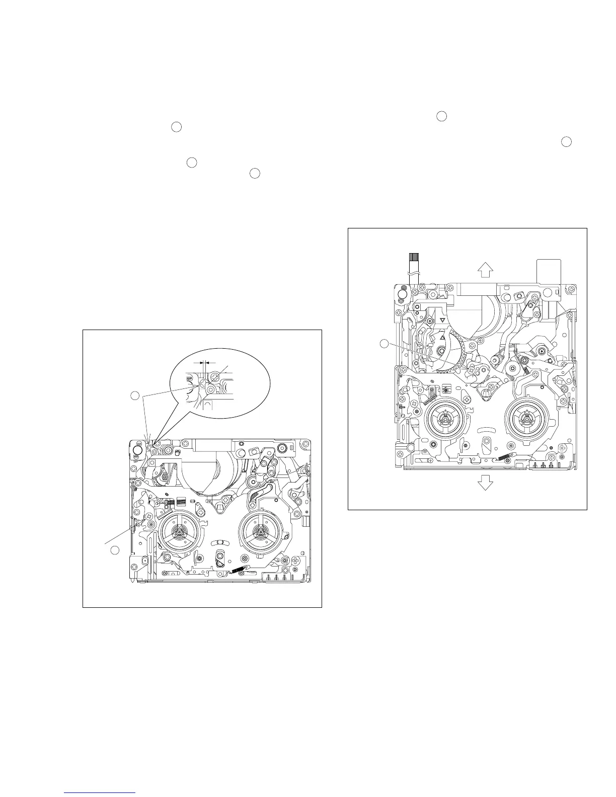
2.6.2 Adjustment of the Tension Arm and Pad Arm As-
semblies
Use Fig. 2-6-2 as the reference unless otherwise specified.
1. Set the PLAY mode.
Se Fig. 2-3-8.
2. Loosen the screw A .
3. With the take-up side at the bottom, align the extreme
end of the Tension Arm Assembly with the crossed
grooves on the screw B that retains the Loading Motor
Assembly and then tighten the screw A .
The tightening torque should be 0.069 N
•
m (0.7 kgf
•
cm).
4. Check the operation.
Repeat unloading and loading several times and make
sure that the Tension Arm Assembly is located within the
normal range.
Note :
With the above checking method, a Torque Me-
ter is not used.
When a Torque meter is used, the following are
the reference values:
Back Tension : 1.96 to 5.88 mN
•
m x 0.1 (2 to 6 g
•
cm)
Play Torque : 6.86 to 10.78 mN
•
m x 0.1 (7 to 11g
•
cm)
Fig. 2-6-2
SCREW
2, 3
A
SCREW
B
TENSIOM
ARM ASSY
Fig. 2-6-3