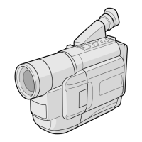
1-4
3a 2 SPEAKER MAIN CN27
3b 5 E. VF (B/W) MAIN CN12
5a 12 TOP OPERATION UNIT MAIN CN18
6a 13 REAR UNIT MAIN CN28
7a 2 MIC MAIN CN8
8a 33 MONITOR ASSEMBLY MAIN CN16
11a 28 MONITOR CN7501 T. HINGE
11b 24 MONITOR CN7502 LCD MODULE
11c 2 MONITOR CN7503 BACK LIGHT
1.3.2 Disassembly method
List of Abbreviations:
2(S1)=2 screws (S1)
4(L1a)=4 Locking Tabs
CN=Connector
1 CASSETTE C1 2(S1)
COVER ASSEMBLY
2
UPPER CASE C2 2(S2), (L2)
3 LOWER CASE C3 9(S3), (L3a), (L3b)
ASSEMBLY (INCL. *CN 3a 3b
E. VF ASSEMBLY) CAP (RCA jack)
4 E. VF ASSEMBLY C4 3(S4)
5 TOP OPERATION C5 2(S5), (L5a), (L5b), (L5c)
UNIT *CN 5a
6 REAR UNIT C6 3(S6), (L6a), (L6b)
*CN 6a
7 FRONT COVER C7 2(S7a), (S7b), (L7a), (L7b)
ASSEMBLY (INCL. MIC *CN 7a
DC LIGHT ASSEMBLY)
8 MICROPHONE (S7a)
9
DC LIGHT ASSEMBLY 2(L7c)
COVER (LIGHT) 2(L7c)
0 MONITOR ASSEMBLY C8 2(S8a), (S8b)
*CN 8a
C9 2(S9a), (S9b), (S9c), (S9d)
C10 2(S10a), 2(S10b), 2(S10c),
(L10a), (L10b), (L10c)
C11 (L11a), (L11b), (L11c)
*CN 11a , 11b , 11c
C12 2(S12a), (S12b), 2(L12a)
- FRONT FRAME C13 2(S13)
ASSEMBLY
STEP
/LOC PART
NO.
REMOVAL
Fig.
No.
Reference Notes:
<NOTE 1>
Destination of connectors
Note:
Two kinds of double-arrows in connection tables
respectively show kinds of connector/wires.
: Flat wire
: Wire
Con- No. of
nector Pins
Connector
*UNLOCK/RELEASE/
UNPLUG/UNCLAMP/
UNSOLDER
Fig. C2
Fig. C1
1
(S1)
2
(S1)
1
<NOTE 2, 3>
(1) The FPC assembly should be winded around the hinge
assembly by two and half turns so that the wire to be
connected to the monitor board assembly is positioned
inside.
(2) The upper and lower hinge covers should be mounted so
carefully the any wire is not caught into either of the
covers.

 Loading...