HA-RF100S(J)
7
8
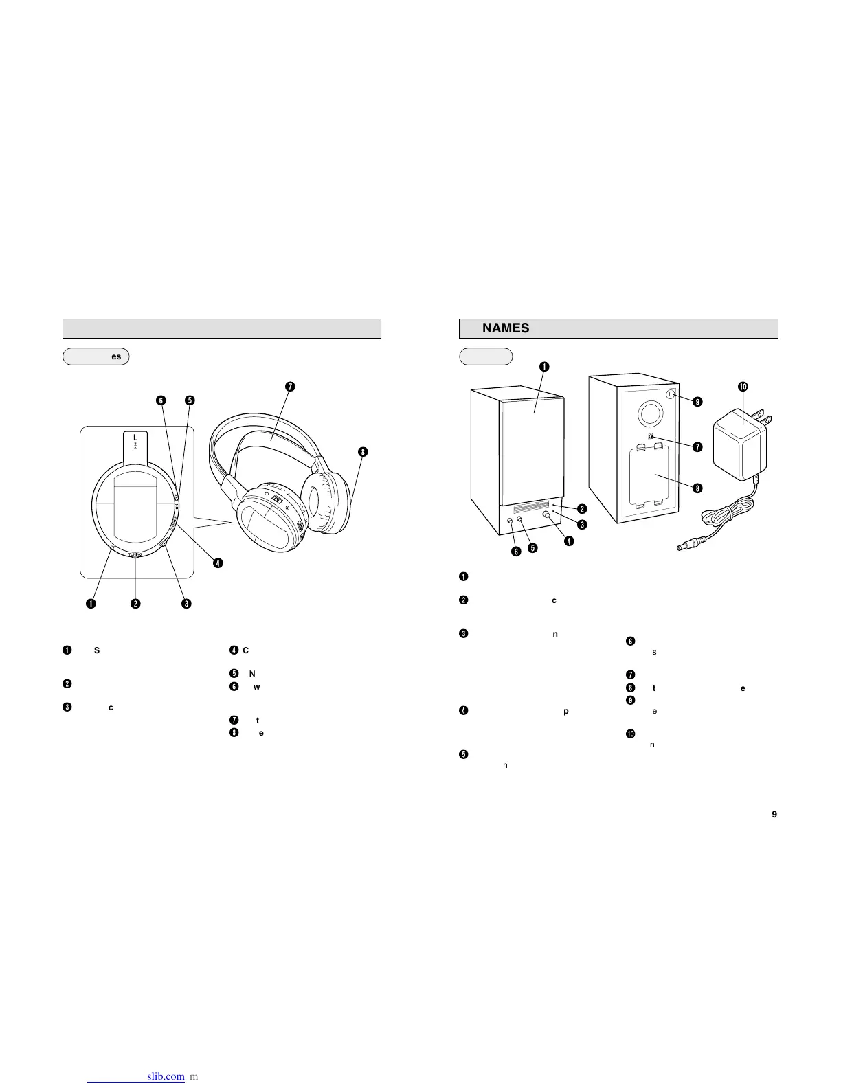
NAMES OF PARTS AND THEIR FUNCTIONS
4
CHARGE (Charging input
terminal)
5
ON/OFF (Power switch)
6
Power indicator
Lights in red when the power is
turned on.
7
Soft Comfort-Fit Headband
8
Battery compartment cover
1
ST. (Stereo signal indicator)
Lights in red when a signal is
received from the transmitter.
2
TUNING (Tuning control)
Adjusts the reception frequency.
3
Volume control
Adjusts the volume level of the left
and right channels simultaneously.
1 2 3
4
8
6 5
7
Headphones
9
NAMES OF PARTS AND THEIR FUNCTIONS
1
SPEAKER COVER
Can also be detached.
2
POWER (Power indicator)
Lights in red when the power is
turned on.
3
STEREO (Stereo signal indicator)
Lights in green when receiving the
signal from the transmitter.
Note:
The indicator also lights in green
with signals not originating from the
transmitter.
4
VOLUME (Volume and power
ON/OFF)
Turn the knob clockwise to turn the
power on and to turn up the volume.
5
AUTO TUNING
Adjusts the reception frequency. When
the button is pressed, frequency tuning
starts automatically and it stops when
a signal is detected.
Note:
Signals not originating from the
transmitter or unexpected signals
can also cause the frequency tuning
to stop. If this happens, press the
button again to resume tuning.
6
BASS BOOST CONTROL
Press this button to emphasize the
bass.
7
DC IN (DC 9 V jack)
8
Battery compartment cover
9
L/R (Channel marking)
Refer to this mark to set the
speaker.
0
AC adaptor (J46906-001)
Connects to a household AC outlet.
(AC 120 V, 60 Hz)
Speakers
6
2
1
0
5
4
3
8
7
9