Do you have a question about the JVC HR-S7611EU and is the answer not in the manual?
General safety guidelines for servicing personnel to follow.
Verifies insulation resistance between plug prongs and exposed parts.
Confirms dielectric strength between plug prongs and exposed parts.
Checks clearance distance for primary circuit components.
Measures leakage current between ground/plug and accessible parts.
Measures grounding impedance for Class I models.
Steps to place the cassette holder in a specific service position.
Detailed steps for removing the mechanism and main board.
Explanation of the special service mode for the mechanism.
Details on how to display emergency fault codes.
Safety measures before starting mechanism adjustments.
Identifies and locates key mechanical components.
Procedure for setting the mechanism into assembling mode.
Detailed steps for removing the cassette holder.
Instructions for removing and installing the pinch roller arm.
Procedures for removing and installing guide arm and press lever assemblies.
Steps for removing and installing the audio control head.
Procedures for removing and installing the loading motor.
Steps for removing and installing the capstan motor.
Instructions for removing and installing pole base assemblies.
Procedures for removing and installing the rotary encoder.
Steps for removing and installing the clutch unit.
Procedures for changing the lever assembly, direct gear, and clutch gear.
Steps for removing and installing the link lever.
Procedures for cassette gear, control cam, and worm gear.
Steps for removing and installing the control plate.
Procedures for loading arm gear and shaft.
Procedures for take-up lever, head, and control plate guide.
Steps for removing and installing capstan brake assembly.
Procedures for sub brake assembly.
Procedures for main brake assembly, reel disk.
Procedures for tension brake, reel disk, and tension arm.
Steps for removing and installing the stator assembly.
Procedures for removing and installing the rotor assembly.
Steps for removing and installing the upper drum assembly.
| Tuner | Yes |
|---|---|
| Hi-Fi Stereo | Yes |
| Number of Heads | 4 |
| Remote Control | Yes |
| ShowView | Yes |
| Stereo Sound | Yes |
| Front AV Inputs | Yes |
| Timer Recording | Yes |
| Auto Head Cleaning | Yes |
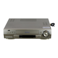
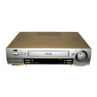
| Type | VCR |
| Video Format | S-VHS / VHS |
| Playback System | PAL, SECAM |
| Connections | SCART, RCA |
| Playback Speeds | SP, LP |
| NTSC Playback | Yes |