1-7
DISASSEMBLY INSTRUCTIONS
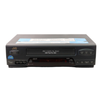
2-14: CAPSTAN DD UNIT (Refer to Fig. 2-14-A)
1.
2.
3.
Remove the Capstan Belt.
Remove the 3 screws 1.
Remove the Capstan DD Unit.
Fig. 2-14-A
Capstan Belt
Capstan DD Unit
• Screw Torque: 4 ± 0.5kgf•cm
1
1
1
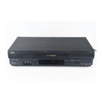
2-15: MAIN CAM/PINCH ROLLER CAM/JOINT GEAR
(Refer to Fig. 2-15-A)
1.
2.
Remove the E-Ring 1, then remove the Main Cam.
Remove the E-Ring 2, then remove the Pinch Roller
Cam and Joint Gear.
Fig. 2-15-A
1
Main Cam
Pinch Roller Cam
Joint Gear
2
NOTE
1. In case of the Pinch Roller Cam and Main Cam installa-
tion, install them as the circled section of Fig. 2-15-B so
that the each markers are met. (Refer to Fig. 2-15-B)
And also can be seen the Main Chassis hole through the
Main Cam maker hole.
Fig. 2-15-B
Pinch Roller Cam
Marker
Main Cam
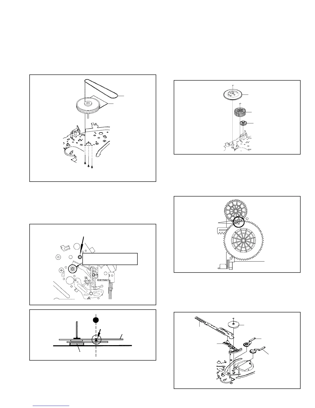
2-16: LOADING GEAR S/T UNIT (Refer to Fig. 2-16-A)
1.
2.
Remove the E-Ring 1 and remove the Main Loading
Gear.
Remove the Main Rod, Tension Lever, Loading Arm S
Unit and Loading Arm T Unit.
1
Main Loading Gear
Main Rod
Tension Lever
Loading Arm T Unit
Loading Arm S Unit
Fig. 2-16-A
NOTE
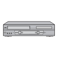
1. In case of the Capstan DD Unit installation, apply the
silicon bond (TSE3843-W) on the position Fig. 2-14-B
correctly. (If no silicon bond applied, abnormal noise will
be heard on the deck operation.)
(Refer to Fig. 2-14-B, C)
Fig. 2-14-B
Applied position of
silicon bond
Be careful not to apply the silicon
bond to the Pinch Roller.
Fig. 2-14-C
Silicon Bond
Main Chassis
Capstan DD Unit
 Loading...