DISASSEMBLY INSTRUCTIONS
1-2
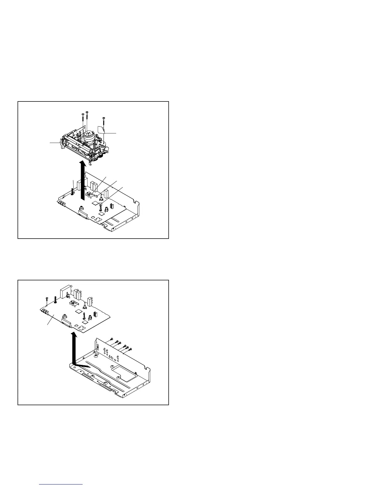
1-5: VCR/DVD PCB (Refer to Fig. 1-5)
1.
2.
3.
Remove the screw 1.
Remove the 6 screws 2.
Remove the VCR/DVD PCB in the direction of arrow.
Fig. 1-5
1
1
1
VCR Deck
CP101
1-4: VCR DECK (Refer to Fig. 1-4)
1.
2.
3.
Remove the 3 screws 2.
Disconnect the following connectors: (CP101, CP102,
CP103 and CP3001).
Remove the AC Head Cover and VCR Deck in the
direction of arrow.
Fig. 1-4
CP102
CP103
CP3001
AC Head Cover
2
VCR/DVD PCB
1
2
2
2
2
2
 Loading...