DISASSEMBLY INSTRUCTIONS
1-1
1
1
2
Top Cabinet
Front Cabinet
1
1
2
2
2
2
2
1
2
1.
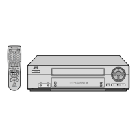
1-1:
Fig. 1-1
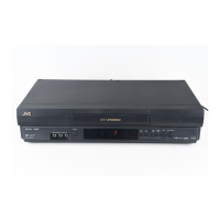
REMOVAL OF MECHANICAL PARTS
AND P.C. BOARDS
TOP CABINET AND FRONT CABINET
(Refer to Fig. 1-1)
1.
2.
3.
4.
5.
6.
7.
Remove the 5 screws 1.
Remove the Top Cabinet in the direction of arrow (A).
Disconnect the following connector: (CP651).
Unlock the 8 supports 2.
Remove the Front Cabinet in the direction of arrow (B).
Remove the 2 screws 3.
Remove the Operation PCB in the direction of arrow (C).
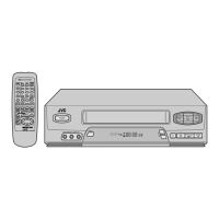
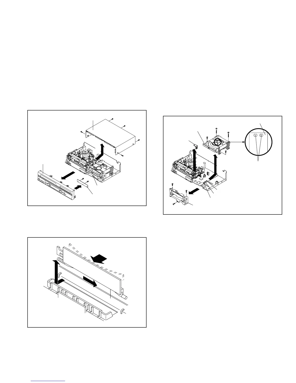
1-2: FLAP (Refer to Fig. 1-2)
1.
2.
Open Flap to 90˚ and flex in direction of arrow (A), at the
same time slide in direction of arrow (B).
Then lift in direction of arrow (C).
Fig. 1-2
(A)
Flap
(B)
(C)
(B)
3
3
Operation PCB
CP651
2
(A)
(C)
1.
2.
3.
4.
5.
6.
7.
8.
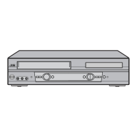
Make the short circuit on the position as shown Fig. 1-3
using a soldering. If you remove the Deck CD with no
soldering, the Laser may be damaged.
Unlock the support 1 and remove the Deck Top Holder
in the direction of arrow (A).
Remove the 2 screws 2.
Remove the 2 screws 3.
Disconnect the following connectors: (CP2301, CP2302,
CP2601).
Remove the Deck CD in the direction of arrow (B).
Remove the 3 screws 4.
Remove the Front Angle in the direction of arrow (C).
Fig. 1-3
1-3: DECK CD (Refer to Fig. 1-3)
NOTE
When the installation of the Deck CD, remove all the solder-
ing on the short circuit position after the connection of Pick
Up PCB and VCR/DVD PCB connector.
2
1
Make the sort circuit
using a soldering.
Pick Up PCB
Deck Top Holder
2
3
(A)
3
4
Deck CD
(C)
Front Angle
4
4
(B)
CP2301
CP2302
CP2601
 Loading...