1-8 (No.22066)
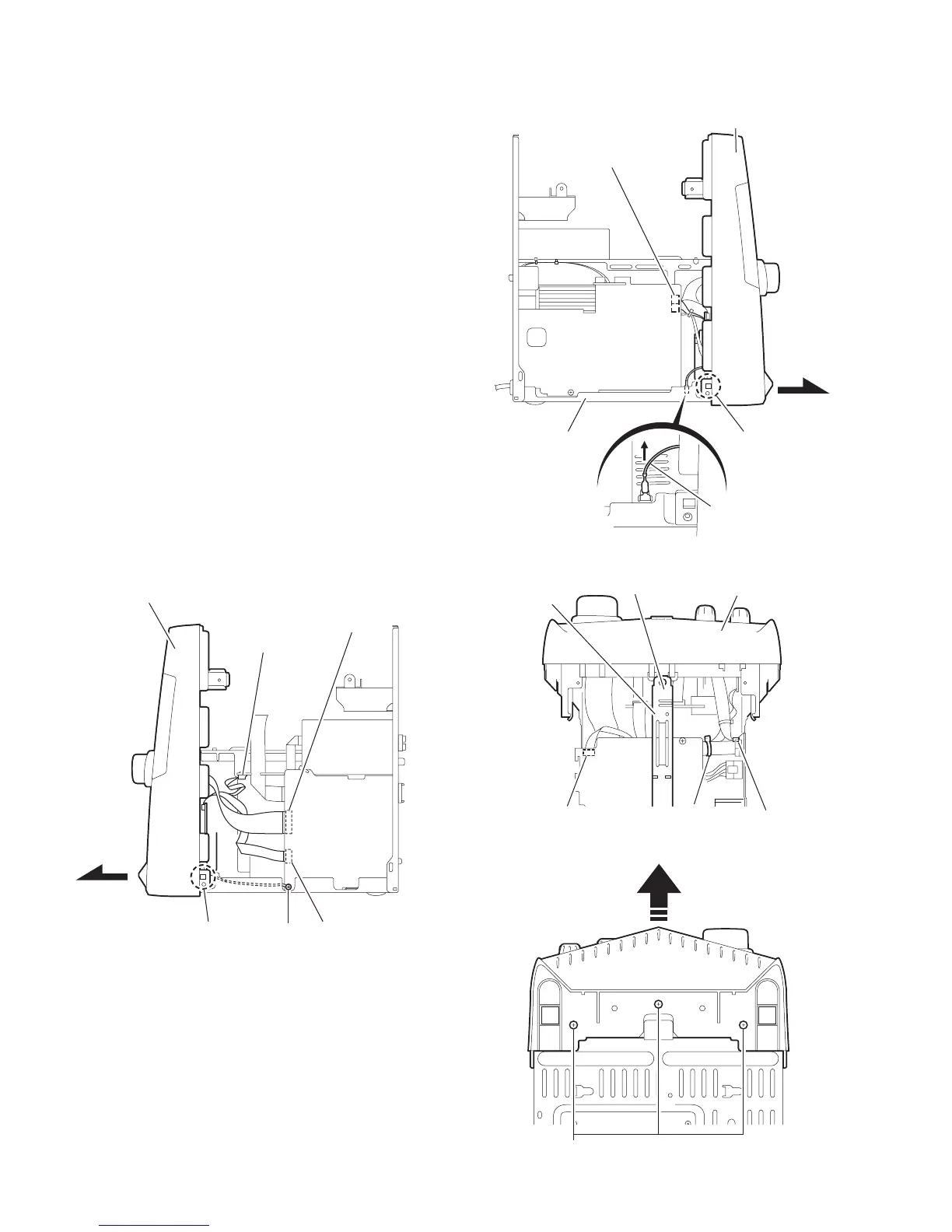
3.1.3 Removing the front panel assembly
(See Fig.6~9)
• Prior to performing the following procedure, remove the metal
cover and the CD changer mechanism assembly.
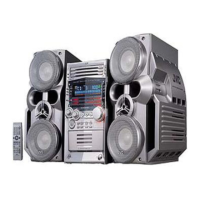
(1) Disconnect the card wires from connector CN44 and
CN870 on the main board on the right side of the body. Re-
move the screw D attaching the wire from extending from
the underside of the front panel assembly.
(2) Disconnect the wire from connector CN701 on the bridge
board.
(3) Cut the band.
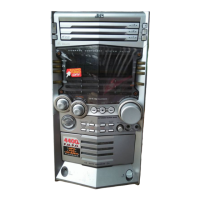
(4) Disconnect the wires from connector CN231 and CN232
on the primary board on the left side of the body.
(5) Remove the plastic rivet attaching the inner bar in the cen-
ter of the front panel assembly.
REFERENCE:
Keep the plastic rivet for reuse.
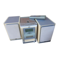
(6) Remove the three screws E attaching the front panel as-
sembly at the bottom of the body.
(7) Disconnect the ground wire extending from the phone
board from bottom chassis.
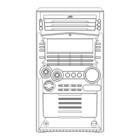
(8) Release the two joints a on the lower left and right sides of
the front panel assembly using a screwdriver, and remove
the front panel assembly toward the front.
REFERENCE:
Front panel need to be tilt little bit as release from bottom
chassis.
Fig.6
Fig.7
Fig.8
Fig.9
Main board
CN870
CN44
Front panel assembly
D
Joint a
Bridge board
CN701
Primary board
CN231,CN232
Front panel aeembly
Joint a
Bottom chassis
Ground wire
Primary board
CN231,CN232
Band
Bridge board
CN701
Inner bar
Plastic rivet
Front panel assembly
E
 Loading...