Do you have a question about the JVC JR-S100 and is the answer not in the manual?
Detailed technical specifications for the receiver's amplifier.
Detailed technical specifications for the FM tuner section.
Detailed technical specifications for the AM tuner section.
Specifications regarding the unit's size and mass.
Steps and parts for removing the top cover and bottom plate.
Procedures and parts list for front panel removal.
Diagram showing main parts in the top view of the unit.
Diagram showing main parts in the bottom view of the unit.
Exploded view and parts list for the front panel assembly.
Exploded view and parts list for the rear panel.
Step-by-step instructions for stringing the dial cord.
Procedures for aligning the FM section, including meter and distortion.
Procedures for adjusting tracking and sensitivity.
Procedures for adjusting multiplex and stereo separation.
Procedures for aligning the AM section.
Procedure for adjusting the center voltage of the power amplifier.
Procedure for adjusting the idling current of the power amplifier.
Part locations and component list for the TRA-16 board.
Part locations and component list for the TXX-31A board.
Part locations and component list for the TPS-531 board.
Part locations and component list for the TSC-64 board.
Part locations and component list for the TAC-404 board.
| Brand | JVC |
|---|---|
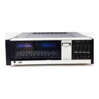
| Model | JR-S100 |
| Category | Stereo Receiver |
| Language | English |